
Operation Manual
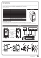


CONTROL BOX
11
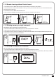
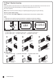
LED Display Definition Parameter Table Description
Time Gap b/w Two Gates
(Closing)
Auto-closing
Safety Device Function Mode
Pedestrian Mode
Flashing Light
Photocell Activation
Photocell 2 Activation
Alarm Buzzer
Electric Latch Mode
LED Direction
Dual / Single Gate
Over Current Reverses Time
when Close
F8
F9
FA
FB
FC
FD
FE
FF
FG
FH
FI
FJ
F8-0
F8-1
F8-2
F8-3
F8-4
F8-5
F8-6
F8-7
F8-8
F8-9
F9-0
F9-1
F9-2
F9-3
F9-4
F9-5
F9-6
F9-7
F9-8
FA-1
FA-2
FA-3
FA-4
FB-0
FB-1
FC-0
FC-1
FD-0
FD-1
FE-0
FE-1
FF-0
FF-1
FG-0
FG-1
FH-0
FH-1
FI-1
FI-2
FJ-0
FJ-1
FJ-2
FJ-3
FJ-4
FJ-5
FJ-6
0 sec
2 sec
5 sec
10 sec
15 sec
20 sec
25 sec
35 sec
45 sec
55 sec
Function OFF
3 sec
10 sec
20 sec
40 sec
60 sec
120 sec
180 sec
300 sec
Mode 1
Mode 2
Mode 3
Mode 4
Function OFF
Function ON
Function OFF
Function ON
Function OFF
Function ON
Function OFF
Function ON
Function OFF
Function ON
Standard Gate Opening
Release Gate Tension before
Opening (Gate Reversing for 0.25s)
When Terminal Block is at Bottom
When Terminal Block is at Top
Single Gate
Dual Gate
Function OFF
0.1 sec
0.2 sec
0.3 sec
0.4 sec
0.5 sec
0.6 sec
1. The factory setting is "F8-1".
1. Auto-close mode activates when the gates move to
the end position or stopped manually. If the
transmitter, push button, or the key selector is
activated before the auto-close counting, the gate
will close immediately.
2. The factory setting is "F9-0".
1. Please see 7.3 photocell adjustment for photocell logic
2. The factory setting is "FA-1".
1. The factory setting is "FB-1".
1. When function FC-1, the light will flash for 3 seconds
before the gate operates. If set OFF, the flash light will
operate with motor at the same time.
2. The factory setting is "FC-0".
1. The factory setting is "FD-0".
1. The factory setting is "FE-0".
1. The factory setting is "FF-0".
1. If the function is FG-1, the motor will be reversed for
0.25 sec. to release the tension.
2.The factory setting is "FG-1".
1. The factory setting is "FH-0".
1. The factory setting is "FI-2".
1. The factory setting is "FJ-0"
Note(F1-3 over-current setting in Hall sensor mode):
Only in “F1-3”Hall sensor mode, the PCB will record all the current value in learning mode. Please adjust over current value by setting F3 function after
learning mode.
The recorded current values will increase according to the value shown on LED display as over current value.