
Operation Manual


CONTROL BOX
2
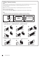
1. Decide the installation position of control box first, it is suggested to be installed near the gate and should
be protected from possible damage. Be aware of the motor cable length before deciding the installation position.
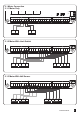
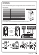
2. Remove the cover by unscrewing the four screws on the cover. See Figure A.
3. Use a screwdriver to puncture the holes beneath the bottom of the control box. See Figure B.
4. Secure it on the wall Figure C.
1). Control Box Installation
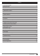
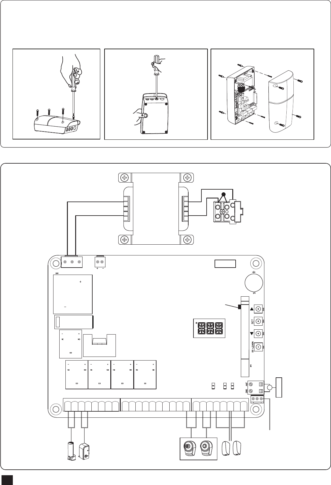
2). Wiring Connection
Figure A Figure B Figure C
Transformer
Antenna
Green Box
+5V INPUT
TX RX
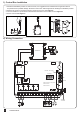
LED Display
LED2 Push button or Key selector
LED4 Photocell 1
LED3 Photocell 2
1 2 3 4 5 6 7 8
9 10 11 12 13 14 15 16 17 18
19 20 21 22 23 24 25 26
UP
SET
DOWN
RF-LEARN
LED2 LED4 LED3
11
Lit+ Lit- Lat+ Lat- M1+ M1- M2+ M2- 5V S1 S2 GND Lmt1 Lmt2 GND Lmt3 Lmt4 GND GNDPh1 Ph2PhVcc PhVccGNDDKey SKey
Blue LED – RF Learning
Wifi Device