
Operation Manual


CONTROL BOX
4
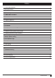
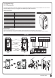
Battery Power: The battery white connector must be fitted the correct way round (positive red to +positive) or
you will short circuit the control board. There are 2 x 12v batteries fitted under the control board. They are connected
together in series to make 24vDC via a black cable with a yellow fuse with positive of one battery to negative of
second battery. The remaining positive and negative terminals go to the control board as per the photo above
12 Volt 2.2Ah Battery
SERIES
12 Volt 2.2Ah Battery
OUTPUT: 24 Volt 2.2Ah
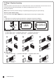
2.2.1 Back-up Batteries
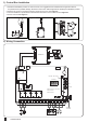
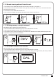
2.2 Wifi Device
1 2 3 4 5 6 7 8
Lit+ Lit- Lat+ Lat- M1+ M1- M2+ M2- 5V S1 S2 GND Lmt1 Lmt2 GND Lmt3
• LED description:
Blue: LED will be flashing during WIFI pairing, and be ON when completed.
Green: LED will be flashing if WB-001 receives signal from APP.
If your home WIFI disconnects, the green light will continuously flash, and it will be off
until WIFI is connected again.
Red: System failure or wrong PIN.
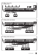
Functions of Buttons and Terminals
Terminals
P button:
WIFI paring: Press 1 sec
Default setting: Press 3 sec
R button:
Press to restart