
Operation Manual


CONTROL BOX
5
Figure 1(7)
The safety photocells are security devices for control automatic gates. Consist of one transmitter and one receiver
based in waterproof covers; it is triggered while breaking the path of the beams.
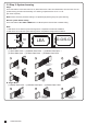
INSTALLATION:
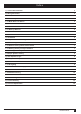
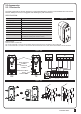
Wire Connection of Photocells
TX: Connect terminals 1 and 2 on the transmitter with the terminals PhVcc and GND on the PC190 PCB.
RX: Connect terminals 1,2,3 and 4 on the receiver with the terminals PhVcc, GND, and Ph1/Ph2 GND on the PC190 PCB.
Detection Method
Sensing Range
Input Voltage
Response Time
Emitting Element
Operation Indicator
Dimensions
Output Method
Current Consumption Max
Water Proof
Through Beam
25M
AC/DC 12~24V
100MS
IR LED
Red LED(RX): ON(When Beam is Broken), Green(TX):ON
96*45*43mm
Relay Output
TX: 35MA/Rx: 38MA (When beam aligned properly);
TX: 35MA/ Rx: 20MA (When beam is broken)
IP54
2.3.1 Photocells
2.3 Accessories
SPECIFICATION:
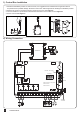
Figure 1(6)
Figure 1(5)
RX
Lens
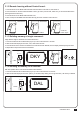
Beam Alignmnet
Indicator
Power Led
Indicator
Terminal Block
Power
Terminal Block
TX
1 2 3 4 5 1 2
DC+ GND
TX
DC+ GND N.O. N.C. COM
RX
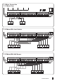
Antenna
Lmt4Lmt3
Lmt2
SKey Ph2Ph1 PhVcc PhVcc
ANT
GND
DKey
GND
GND
GND
Lmt1
GND
PC190-PCB1
40121-377-A1
SW1
RF-LEARN
RF1
J3
J7
J8
SW4
SET
SW5
DOWN
NO
+
9 10 11 12 13 14 15 16 17 18
19 20 21 22 23 24 25 26
LED2
LED3
LED4