
Installation Sheet


PROFLO.COM6
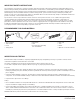
FRAMING AND INSTALLATION
Structural measurements should be veried against the actual bath received to ensure proper t.
• Never lift the tub by the plumbing. Doing so can result in leaks.
• Check if the oor is level and of good quality. An uneven oor may impede proper installation of the tub.
• Clean installation area of any debris or trash.
Locate studs as needed. Ensure roughing-in dimensions are proper, plumb and square. Provisions must be made in all installations for an
access opening for servicing the pump and controls on the pump or blower side.
An access opening of at least 18" x 24" must be provided or warranty service will not be performed. It is strongly recommended that an
additional opening be provided for access to the drain components. The apron should not be used as the primary access opening.
If the sub-oor is not level, you must level the entire surface prior to installing the bathtub.
Ensure that the entire oor is level and can support a load of 80lbs. per square foot.
The bathtub must remain level in order for it to drain properly and must make contact with the leveling material.
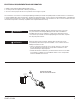
1. Position the tub into the installation opening and level the deck in both directions, shimming the base of the tub if necessary. Mark the
nal position of the underside of the deck by tracing a line on to the studs (see Figure 1).
2. Remove the tub and attach a 1 x 4 stringer to the studs, with the top of the stringer touching the traced line. Never support the tub by its
deck lip or stringers (see gure 2).
3. Install drain components to the tub following the drain installation instructions. Note that this requires a cutout in the oor.
Before replacing your tub for nal installation, bathtubs require a 6" x 12" oor opening for the 1-1/2" drain and waste & overow kit.
The drain/overow of the bath extends below the bottom of the bath.
The bath must be supported along its entire bottom. Do not remove foam base & pad from the bottom of the tub. Use 1-1/2" to 2" of
mortar as bedding material (do not use sand or foam). After the mortar has been poured, and before it sets, position tub within recess until
the rim is leveled against the leveling stringers (see below).
FIGURE 1
STRINGER INSTALLATION
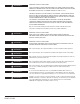
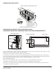
TYPICAL DROP-IN TYPE INSTALLATION
REFERENCE FOR DROP-IN INSTALLATION
FIGURE 2
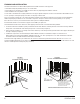
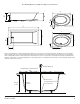
TYPICAL ALCOVE INSTALLATION
18"
(457.2mm)
24"
(609.6mm)
24"
(609.6mm)
LEVELING
STRINGERS
ACCESS PANEL MUST BE LOCATED
ON THE SAME SIDE AS THE MOTOR.
ALLOW OPEN FRAMING ON
PUMP MOTOR END FOR SERVICE.
ACCESS PANELS NOT REQUIRED
FOR NON-SYSTEM TUBS.
NOTE:
FRONT EDGE OF BATH
MUST BE SUPPORTED
BY STUD WALL.
HEIGHT
TO LIP
TILE
WALLBOARD
G
CUTOUT
18"
(457.2MM)
AS DESIRED
MOUNTING
SURFACE
WATERPROOF
SEALANT
BATH
AS DESIRED
F
CUTOUT
C
SILICONE
1" X 4" JOIST
STUD
AIR GAP 1/4" OR MORE
UNLESS AS ACCESS OPENING OF AT LEST 18" X 24"
IS PROVIDED, WARRANTY SERVICE WILL NOT BE PERFORMED.
ACCESS PANEL MUST BE LOCATED
ON THE SAME SIDE AS THE MOTOR.
ALLOW OPEN FRAMING ON
PUMP MOTOR END FOR SERVICE.
ACCESS PANELS NOT REQUIRED
FOR NON-SYSTEM TUBS.
UNLESS AS ACCESS OPENING OF AT LEST 18" X 24"
IS PROVIDED, WARRANTY SERVICE WILL NOT BE PERFORMED.
E
C
D
W