
Installation Sheet


PROFLO.COM 7
FRAMING AND INSTALLATION
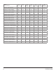
REFERENCE FOR CORRECT TILE FLANGE INSTALLATION
USE DRAWING BELOW AS A REFERENCE GUIDE FOR ROUGH-IN MEASUREMENTS
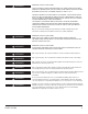
Allow the mortar material to completely harden before applying weight to the rim or bottom of the bath. Any nish material such as tile or
wall board must be self supporting if it contacts the deck of the bath.
Verify that the product is lever by checking the tub deck surface in all directions.
For system tubs ensure blower and or pump cords are properly plugged into the dedicated 120V/20A GFCI outlet to supply electrical
power to the system (Please reference pg. 6) for electrical requirement information. To test run the bath, ll the tub with water at least 3"
above the highest jet and operate the bath for 5 minutes. Check all bath and piping connections for leaks.
POST INSTALLATION CLEAN-UP
Remove all construction debris from bath. Do not use wire brushes or any other metal implement on bath surface.
Post installation clean-up generally can be completed using warm water and liquid dishwashing detergent.
Stubborn dirt or stains may be removed using granular Spic and Span
®
mixed with water. Painter’s Naphtha can be used to remove
excess adhesives and/or wet oil-base paint.
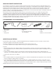
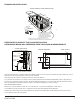
STUD
SUGGESTED WHIRLPOOL/BATH
INSTALLATION METHOD
WATERPROOF DRYWALL
OR CEMENT BOARD
TILE
ROOFING NAIL
SEALANT
TUB
1 X 4 (25mm X 76mm)
WOOD STINGER FULL LENGTH
FIGURE 1
STRINGER INSTALLATION
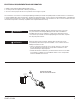
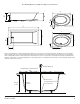
TYPICAL DROP-IN TYPE INSTALLATION
REFERENCE FOR DROP-IN INSTALLATION
FIGURE 2
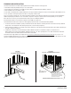
TYPICAL ALCOVE INSTALLATION
18"
(457.2mm)
24"
(609.6mm)
24"
(609.6mm)
LEVELING
STRINGERS
ACCESS PANEL MUST BE LOCATED
ON THE SAME SIDE AS THE MOTOR.
ALLOW OPEN FRAMING ON
PUMP MOTOR END FOR SERVICE.
ACCESS PANELS NOT REQUIRED
FOR NON-SYSTEM TUBS.
NOTE:
FRONT EDGE OF BATH
MUST BE SUPPORTED
BY STUD WALL.
HEIGHT
TO LIP
TILE
WALLBOARD
G
CUTOUT
18"
(457.2MM)
AS DESIRED
MOUNTING
SURFACE
WATERPROOF
SEALANT
BATH
AS DESIRED
F
CUTOUT
C
SILICONE
1" X 4" JOIST
STUD
AIR GAP 1/4" OR MORE
UNLESS AS ACCESS OPENING OF AT LEST 18" X 24"
IS PROVIDED, WARRANTY SERVICE WILL NOT BE PERFORMED.
ACCESS PANEL MUST BE LOCATED
ON THE SAME SIDE AS THE MOTOR.
ALLOW OPEN FRAMING ON
PUMP MOTOR END FOR SERVICE.
ACCESS PANELS NOT REQUIRED
FOR NON-SYSTEM TUBS.
UNLESS AS ACCESS OPENING OF AT LEST 18" X 24"
IS PROVIDED, WARRANTY SERVICE WILL NOT BE PERFORMED.
E
C
D
W
DRAIN CLEARANCE
11”
12”
PUMP ACCESS
SUGGESTED ALCOVE
INSTALLATION METHOD
UNLESS AS ACCESS OPENING OF AT LEAST 18" X 24"
IS PROVIDED, WARRANTY SERVICE WILL NOT BE PERFORMED.