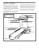
www.proform.com Model No. PFTL99013.0 Serial No. Write the serial number in the space above for reference. Serial Number Decal ACTIVATE YOUR WARRANTY To register your product and activate your warranty today, go to www.proformservice.com/ registration. CUSTOMER CARE For service at any time, go to www.proformservice.com. Or call 1-888-533-1333 Mon.–Fri. 6 a.m.–6 p.m. MT Sat. 8 a.m.–12 p.m. MT Please do not contact the store.
TABLE OF CONTENTS WARNING DECAL PLACEMENT . . . . . . . . . . . . . . . . . . . . . . . . . . . . . . . . . . . . . . . . . . . . . . . . . . . . . . . . . . . . . . . 2 IMPORTANT PRECAUTIONS . . . . . . . . . . . . . . . . . . . . . . . . . . . . . . . . . . . . . . . . . . . . . . . . . . . . . . . . . . . . . . . . . . 3 BEFORE YOU BEGIN. . . . . . . . . . . . . . . . . . . . . . . . . . . . . . . . . . . . . . . . . . . . . . . . . . . . . . . . . . . . . . . . . . . . . . . .
IMPORTANT PRECAUTIONS WARNING: To reduce the risk of burns, fire, electric shock, or injury to persons, read all important precautions and instructions in this manual and all warnings on your treadmill before using your treadmill. ICON assumes no responsibility for personal injury or property damage sustained by or through the use of this product. 1. It is the responsibility of the owner to ensure that all users of this treadmill are adequately informed of all warnings and precautions. 12.
20. The heart rate monitor is not a medical device. Various factors, including the user’s movement, may affect the accuracy of heart rate readings. The heart rate monitor is intended only as an exercise aid in determining heart rate trends in general. 24. Never insert any object into any opening on the treadmill. 25. Inspect and properly tighten all parts of the treadmill regularly. 26. 21. Never leave the treadmill unattended while it is running.
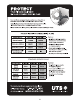
STANDARD SERVICE PLANS all 6
BEFORE YOU BEGIN Thank you for selecting the revolutionary PROFORM® 11.0 TT treadmill. The 11.0 TT treadmill offers an impressive selection of features designed to make your workouts at home more effective and enjoyable. And when you’re not exercising, the unique treadmill can be folded up, requiring less than half the floor space of other treadmills. reading this manual, please see the front cover of this manual.
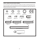
PART IDENTIFICATION CHART Use the drawings below to identify small parts used for assembly. The number in parentheses below each drawing is the key number of the part, from the PART LIST near the end of this manual. The number following the key number is the quantity used for assembly. Note: If a part is not in the hardware kit, check to see whether it is preattached. Extra parts may be included.
ASSEMBLY • Assembly requires two persons. • To identify small parts, see page 8. • Place all parts in a cleared area and remove the packing materials. Do not dispose of the packing materials until you finish all assembly steps. • Assembly requires the following tools: the included hex key one adjustable wrench • After shipping, there may be an oily substance on the exterior of the treadmill. This is normal.
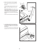
2. Make sure that the power cord is unplugged. 2 Wire 81 Tie Press a Base Cap (74) into each side of the Base (94). A Identify the Right Upright (90). Have a second person hold the Right Upright near the Base (94). 81 90 See the inset drawing. Tie the wire tie in the Right Upright (90) securely around the end of the Upright Wire (81). Then, insert the Upright Wire into the lower end of the Right Upright as you pull the other end of the wire tie out of the Right Upright.
4. Insert a Wheel Spacer (63) into a Front Wheel (62). Hold the Front Wheel inside the lower end of the Right Upright (90), and insert a 3/8" x 4" Screw (7) with a 3/8" Star Washer (13) into the Right Upright and the Front Wheel. 4 Repeat this step on the other side of the treadmill (not shown). 90 13 62 63 7 5. Place a piece of packing material (B) under the right side of the Base (94). Hold the Right Upright (90) against the Base. Make sure not to pinch the Upright Wire (81).
6. Remove and discard the four indicated screws (C). 6 C Identify the Left and Right Base Covers (82, 83). Slide the Left Base Cover onto the Left Upright (89), and slide the Right Base Cover onto the Right Upright (90). Do not press the Base Covers into place yet. C 89 Slide the Left and Right Upright Covers (84, 85) onto the Left and Right Uprights (89, 90). 84 90 82 85 83 7. Remove and discard the eight indicated screws (C).
8. Set the console assembly face down on a soft surface to avoid scratching the console assembly. Remove and discard the two indicated Screws (D). Next, lift off the Pulse Crossbar (93). 8 4 Console Assembly D Remove and save the four indicated 1/4" x 1/2" Screws (4); the Screws will be used in a later step. D 4 93 9. IMPORTANT: To avoid damaging the Pulse Crossbar (93), do not use power tools and do not overtighten the #10 x 3/4" Screws (9). 9 9 5 Orient the Pulse Crossbar (93) as shown.
10. With the help of a second person, hold the console assembly near the Right Handrail (87). 10 Console Assembly See the inset drawing. Connect the Upright Wire (81) to the console wire. The connectors should slide together easily and snap into place. If they do not, turn one connector and try again. IF YOU DO NOT CONNECT THE CONNECTORS PROPERLY, THE CONSOLE MAY BECOME DAMAGED WHEN YOU TURN ON THE POWER. Then, remove the wire tie from the Upright Wire. Console Wire 81 Wire Tie Console Wire 81 87 11.
12. Slide the Left and Right Handrail Covers (79, 88) onto the Handrails (86, 87) until the Handrail Covers are flush with the console assembly. 12 Console Assembly Then, attach each Handrail Cover (79, 88) with a #8 x 1/2" Screw (1). 79 86 1 88 87 1 13. Attach the Pulse Crossbar (93) with six #8 x 1/2" Screws (1) into the Pulse Crossbar (93) as shown. Start all six Screws, and then tighten them.
14. Hold the Left Upright Cover (84) against the console assembly. Align the holes in the Left Upright Cover with the holes in the Left Upright (89). Attach the Left Upright Cover with three #8 x 1/2" Screws (1) as shown. 14 Attach the Right Upright Cover (85) to the Right Upright (90) in the same way. 84 Console Assembly 85 1 1 90 15. Attach the Left and Right Trays (36, 27) to the console assembly with four #8 x 1/2" Screws (1). Make sure not to pinch the Upright Wire (81) on the right side.
16. Note: If assembled on a smooth surface, the treadmill may roll forward during this step. 16 Raise the Frame (56) to the upright position. IMPORTANT: Do not raise the Frame past the vertical position. Have a second person hold the Frame until step 17 is completed. Brackets E 38 Remove the two 5/16" x 3/4" Screws (25) from the Latch Crossbar (38). 11 25 Orient the Latch Crossbar (38) as shown. Make sure that the “This side toward belt” sticker (E) is facing the treadmill.
. Align the upper end of the Storage Latch (53) with the bracket on the Latch Crossbar (38). Insert a 5/16" x 2 1/4" Bolt (3) through the bracket. This should push a spacer (F) out of the other end. Discard the spacer. 18 12 38 Attach the Storage Latch (53) with the 5/16" x 2 1/4" Bolt (3) and a 5/16" Nut (12). 3 F 56 53 Lower the Frame (56) (see HOW TO LOWER THE TREADMILL FOR USE on page 28). 19. Firmly tighten the six 3/8" x 4" Screws (7) (only one side is shown).
OPERATION AND ADJUSTMENT HOW TO CONNECT THE POWER CORD nominal 120-volt circuit capable of carrying 15 or more amps. To avoid overloading the circuit, do not plug other electrical devices, except for lowpower devices such as cell phone chargers, into the surge suppressor or into an outlet on the same circuit. IMPORTANT: The treadmill is not compatible with GFCI-equipped outlets and may not be compatible with AFCI-equipped outlets.
CONSOLE DIAGRAM FEATURES OF THE CONSOLE You can even listen to your favorite workout music or audio books with the console’s sound system while you exercise. The treadmill console offers an impressive array of features designed to make your workouts more effective and enjoyable. When you use the manual mode, you can change the speed and incline of the treadmill with the touch of a button. As you exercise, the console will display instant exercise feedback.
HOW TO TURN ON THE POWER HOW TO USE THE MANUAL MODE IMPORTANT: If the treadmill has been exposed to cold temperatures, allow it to warm to room temperature before you turn on the power. If you do not do this, you may damage the console displays or other electrical components. 1. Insert the key into the console. Plug in the power cord (see page 19). Next, locate the power switch on the treadmill frame near the power cord. Press the power switch into the reset position.
5. Follow your progress with the displays. As you exercise, the workout intensity level bar will indicate the approximate intensity level of your exercise. As you walk or run on the treadmill, the display can show the following workout information: • The elapsed time • The distance that you have walked or run • The workout intensity bar Press the Home button to return to the default menu (see THE SETTINGS MODE on page 26 to set the default menu). If necessary, press the Home button again.
7. Turn on the fan if desired. HOW TO USE AN ONBOARD WORKOUT The fan features multiple speed settings. 1. Insert the key into the console. See HOW TO TURN ON THE POWER on page 21. Press the fan buttons repeatedly to select a fan speed or to turn off the fan. 2. Select an onboard workout. To select an onboard workout, press the Speed button, the Incline button, the Intensity button, or the Calorie button repeatedly until the desired workout appears in the display. 8.
The workout will continue in this way until the last segment of the profile flashes in the display and the last segment ends. The walking belt will then slow to a stop. HOW TO USE A SET-A-GOAL WORKOUT 1. Insert the key into the console. See HOW TO TURN ON THE POWER on page 21. Note: The calorie goal is an estimate of the number of calories that you will burn during the workout. The actual number of calories that you burn will depend on various factors such as your weight.
HOW TO USE AN IFIT WORKOUT For more information about the iFit workouts, please see www.iFit.com. Note: To use an iFit workout, you must have an optional iFit module. To purchase an iFit module at any time, go to www.iFit.com or call the telephone number on the front cover of this manual. You must also have access to a computer with a USB port and an internet connection. In addition, you must have access to a wireless network including an 802.
7. Measure your heart rate if desired. THE SETTINGS MODE See step 6 on page 22. The console features a settings mode that keeps track of treadmill information and allows you to personalize console settings. 8. Turn on the fan if desired. See step 7 on page 23. 1. Select the settings mode. 9. When you are finished exercising, remove the key from the console. To select the settings mode, press the Settings button.
DEMO—The console features a display demo mode, designed to be used if the treadmill is displayed in a store. While the demo mode is turned on, the console will function normally when you plug in the power cord, press the power switch into the reset position, and insert the key into the console. However, when you remove the key, the displays will remain lit, although the buttons will not function. If the demo mode is turned on, the word ON will appear in the matrix.
HOW TO FOLD AND MOVE THE TREADMILL HOW TO FOLD THE TREADMILL HOW TO MOVE THE TREADMILL To avoid damaging the treadmill, adjust the incline to zero before you fold the treadmill. Then, remove the key and unplug the power cord. CAUTION: You must be able to safely lift 45 lbs. (20 kg) to raise, lower, or move the treadmill. Before moving the treadmill, fold it as described at the left. CAUTION: Make sure that the storage latch is locked in the storage position. Moving the treadmill may require two people.
TROUBLESHOOTING Most treadmill problems can be solved by following the simple steps below. Find the symptom that applies, and follow the steps listed. If further assistance is needed, see the front cover of this manual. c. Remove the key from the console, and then reinsert it. d. If the treadmill still will not run, please see the front cover of this manual. SYMPTOM: The power does not turn on SYMPTOM: The console displays remain lit when you remove the key from the console a.
Locate the Reed Switch (52) and the Magnet (50) on the left side of the Pulley (49). Turn the Pulley until the Magnet is aligned with the Reed Switch. Make sure that the gap between the Magnet and the Reed Switch is about 1/8 in. (3 mm). If necessary, loosen the #8 x 3/4" Tek Screw (14), move the Reed Switch slightly, and then retighten the Screw. Reattach the Motor Hood (not shown) with the #8 x 3/4" Screws (not shown) and run the treadmill for a few minutes to check for a correct speed reading. b.
SYMPTOM: The walking belt is off-center or slips when walked on b. If the walking belt slips when walked on, first remove the key and UNPLUG THE POWER CORD. Using the hex key, turn both idler roller screws clockwise, 1/4 of a turn. When the walking belt is correctly tightened, you should be able to lift each edge of the walking belt 2 to 3 in. (5 to 7 cm) off the walking platform. Be careful to keep the walking belt centered.
EXERCISE GUIDELINES Burning Fat—To burn fat effectively, you must exercise at a low intensity level for a sustained period of time. During the first few minutes of exercise, your body uses carbohydrate calories for energy. Only after the first few minutes of exercise does your body begin to use stored fat calories for energy. If your goal is to burn fat, adjust the intensity of your exercise until your heart rate is near the lowest number in your training zone.
SUGGESTED STRETCHES The correct form for several basic stretches is shown at the right. Move slowly as you stretch—never bounce. 1. Toe Touch Stretch Stand with your knees bent slightly and slowly bend forward from your hips. Allow your back and shoulders to relax as you reach down toward your toes as far as possible. Hold for 15 counts, then relax. Repeat 3 times. Stretches: Hamstrings, back of knees and back. 1 2. Hamstring Stretch Sit with one leg extended.
PART LIST Key No. Qty. 1 2 3 4 5 6 7 8 9 10 11 12 13 14 15 16 17 18 19 20 21 22 23 24 25 26 27 28 29 30 31 32 33 34 35 36 37 38 39 40 41 42 43 44 45 46 47 48 49 50 21 35 1 4 4 1 6 2 4 11 12 2 6 9 2 1 2 1 4 2 2 2 4 12 2 2 1 4 1 4 4 2 6 4 4 1 2 1 4 2 2 1 1 1 1 2 1 4 1 1 Model No. PFTL99013.0 R1113B Description Key No. Qty.
Key No. Qty. 101 102 103 104 105 106 107 108 1 5 1 1 1 1 2 6 Description Key No. Qty. Right Foot Pad #8 x 3/4" Truss Head Screw Left Rear Cap Right Rear Cap 1/4" x 1 3/4" Screw 1/4" Star Washer #8 x 1 3/4" Screw #8 x 3/4" Washer Head Screw 109 110 111 112 113 114 * 2 1 1 1 1 1 – Description Base Pad Left Foot Pad Filter Bracket Filter Ferrite Incline Stop Bracket User’s Manual Note: Specifications are subject to change without notice.
15 36 2 103 24 59 30 34 23 39 44 2 110 104 35 61 14 2 26 57 24 39 15 35 43 14 2 99 2 24 60 108 25 11 101 23 45 108 42 24 47 46 59 30 34 30 34 102 35 39 2 26 19 108 59 12 14 108 21 23 51 100 14 39 3 35 2 14 95 49 25 11 50 55 53 108 107 52 56 38 10 19 111 23 46 108 20 12 54 48 59 30 34 6 21 105 106 100 102 10 10 112 107 10 EXPLODED DRAWING A Model No. PFTL99013.
EXPLODED DRAWING B Model No. PFTL99013.
EXPLODED DRAWING C Model No. PFTL99013.
EXPLODED DRAWING D Model No. PFTL99013.
ORDERING REPLACEMENT PARTS To order replacement parts, please see the front cover of this manual.