www.proform.com Model No. PFEL89910.1 Serial No. Write the serial number in the space above for reference. Serial Number Decal (on underside of frame) QUESTIONS? If you have questions, or if parts are damaged or missing, DO NOT CONTACT THE STORE; please contact Customer Care. IMPORTANT: Please register this product (see the limited warranty on the back cover of this manual) before contacting Customer Care. 1-888-533-1333 CALL TOLL-FREE: Mon.–Fri. 6 a.m.–6 p.m. MT Sat. 8 a.m.–4 p.m.
TABLE OF CONTENTS WARNING DECAL PLACEMENT . . . . . . . . . . . . . . . . . . . . . . . . . . . . . . . . . . . . . . . . . . . . . . . . . . . . . . . . . . . . . .2 IMPORTANT PRECAUTIONS . . . . . . . . . . . . . . . . . . . . . . . . . . . . . . . . . . . . . . . . . . . . . . . . . . . . . . . . . . . . . . . .3 BEFORE YOU BEGIN . . . . . . . . . . . . . . . . . . . . . . . . . . . . . . . . . . . . . . . . . . . . . . . . . . . . . . . . . . . . . . . . . . . . . .4 ASSEMBLY . . . . . . . . . . . . .
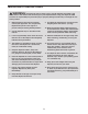
IMPORTANT PRECAUTIONS WARNING: To reduce the risk of serious injury, read all important precautions and instructions in this manual and all warnings on your elliptical before using your elliptical. ICON assumes no responsibility for personal injury or property damage sustained by or through the use of this product. 9. The elliptical should not be used by persons weighing more than 325 lbs. (147 kg). 1. Before beginning any exercise program, consult your physician.
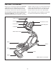
BEFORE YOU BEGIN manual. To help us assist you, note the product model number and serial number before contacting us. The model number and the location of the serial number decal are shown on the front cover of this manual. Thank you for selecting the revolutionary PROFORM® 1100 E elliptical. The 1100 E elliptical provides an impressive selection of features designed to make your workouts at home more effective and enjoyable. For your benefit, read this manual carefully before you use the elliptical.
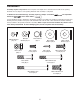
ASSEMBLY Assembly requires two persons. Place all parts of the elliptical in a cleared area and remove the packing materials. Do not dispose of the packing materials until assembly is completed. In addition to the included tool(s), assembly requires a Phillips screwdriver wrenches , and a rubber mallet . , two adjustable See the drawings below to identify the small parts needed for assembly.
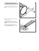
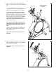
1. 1 To make assembly easier, read the information on page 5 before you begin. Attach the Front Stabilizer (6) to the Front Frame (1) with two M8 x 80mm Patch Screws (84). 6 1 2. Orient the Rear Stabilizer (62) and the Rear Frame (2) as shown. 2 Tip: If the Ramp Cover (see step 15) is attached to the Ramp (3), remove the Ramp Cover. 62 Attach the Rear Stabilizer (62) to the Rear Frame (2) with two M8 x 56mm Patch Screws (94) and two M8 Split Washers (83).
3. Insert the Rear Frame (2) into the Front Frame (1); make sure that the Ramp (3) is on the Lift Roller (12). 3 Attach the Rear Frame (2) with five M8 x 19mm Patch Screws (82) and five M8 Split Washers (83). 3 82 83 12 1 2 83 4. Have a second person orient the Upright (4) as shown and hold it near the Front Frame (1). 83 82 82 4 Locate the wire tie in the Upright (4). Tie the lower end of the wire tie to the Wire Harness (110).
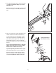
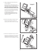
5. Apply a generous amount of grease to the Pivot Axle (35) and to two Wave Washers (95). 5 Insert the Pivot Axle (35) through the Upright (4) and then center it. Slide a Wave Washer (95) onto each end of the Pivot Axle (35). Grease 4 95 35 Grease 95 6. Identify the Right Upper Body Arm (61) and the Right Upper Body Leg (60), which are marked with “Right” stickers, and orient them as shown. Make sure that the hexagonal holes are in the position shown.
7. Have a second person hold the Right Upper Body Leg (60) near the right side of the Upright (4). 7 Locate the wire tie in the right side of the Upright (4). Tie the wire tie to the Right Control Wire (41) in the Right Upper Body Leg (60). Tip: Do not pinch the Right Control Wire (41). Pull the upper end of the wire tie until the Right Control Wire is routed through the Upright (4).
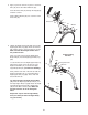
9. Have a second person hold the Console (7) near the Upright (4). 9 Connect the wires on the Console (7) to the Wire Harness (110), to the Pulse Wire (63), and to the Right and Left Control Wires (41, 48). Make sure to connect the console wire that has a tag to the Control Wire that has a tag. 7 Avoid pinching the wires 63 Insert the excess Pulse Wire (63) upward into the Console (7) while inserting the other wires downward into the Upright (4). 110 48 41 Tip: Avoid pinching the wires.
12. Apply a small amount of grease to the right Crank Arm (20). Orient a Roller Arm (45) so that the Roller (51) is in the position shown. 12 Slide the Roller Arm (45) onto the right Crank Arm (20) while setting the Roller (51) on the Ramp (3). 20 Attach the Roller Arm (45) with an M8 x 19mm Patch Screw (82), an Axle Cover (53), and an M8 x 25mm Washer (98); to avoid breaking the Axle Cover, do not overtighten the Patch Screw. 98 53 45 Repeat this step on the other side of the elliptical. 3 13.
14. See the upper drawing. Apply a small amount of grease to the axle on the Right Upper Body Leg (60) and to the axle on the Right Pedal Arm (58). 14 60 Orient the Right Pedal Arm (58) as shown. Slide the Right Pedal Arm onto the Right Upper Body Leg (60) and into the right Roller Arm (45) at the same time.
HOW TO USE THE ELLIPTICAL HOW TO PLUG IN THE POWER CORD HOW TO MOVE THE ELLIPTICAL This product must be grounded. If it should malfunction or break down, grounding provides a path of least resistance for electric current to reduce the risk of electric shock. This product is equipped with a cord having an equipment-grounding conductor and a grounding plug. Due to the size and weight of the elliptical, moving it requires two persons.
HOW TO EXERCISE ON THE ELLIPTICAL To mount the elliptical, hold the upper body arms and step onto the pedal that is in the lower position. Then, step onto the other pedal. Push the pedals until they begin to move with a continuous motion. Note: The discs can turn in either direction. It is recommended that you turn the discs in the direction shown by the arrow; however, for variety, you can turn the discs in the opposite direction.
CONSOLE DIAGRAM FEATURES OF THE CONSOLE network through an iFit Live module. The optional iFit Live module allows you to download personalized workouts and to track and analyze workout information on the iFit Live website. To purchase an iFit Live module at any time, go to www. iFit.com or call the telephone number on the front cover of this manual. The advanced console offers an array of features designed to make your workouts more effective and enjoyable.
HOW TO TURN ON THE POWER To vary the motion of the pedals, you can change the incline of the ramp. To change the incline, press one of the numbered Quick Ramp buttons or press the Quick Ramp Increase and Decrease buttons located on the console or on the left upper body arm. IMPORTANT: If the elliptical has been exposed to cold temperatures, allow it to warm to room temperature before turning on the power. If you do not do this, you may damage the console displays or other electrical components.
5. Measure your heart rate if desired. 6. Turn on the fan if desired. If there are sheets of plastic Contacts on the metal contacts on the handgrip pulse sensor, remove the plastic. To measure your heart rate, hold the handgrip pulse sensor with your palms resting against the metal contacts. Avoid moving your hands or gripping the contacts tightly. The fan has high and low speed settings. Press the Fan button repeatedly to select a fan speed or to turn off the fan. 7.
HOW TO USE A PRESET WORKOUT When the first segment of the workout ends, the resistance level, ramp incline, and the target rpm for the second segment will appear in the display for a few seconds to alert you. The next segment of the profile will begin to flash, and the pedals will automatically adjust to the resistance level and the ramp incline for the next segment. 1. Begin pedaling or press any button on the console to turn on the console. See HOW TO TURN ON THE POWER on page 16. 2.
HOW TO USE THE IFIT TRAINING MODE HOW TO USE THE INFORMATION MODE The optional iFit Live module allows your console to communicate with your wireless network and unlocks exciting new features. For example, you can download personalized workouts, create your own workouts, track your workout results, and access many other features on the iFit Live website. To purchase an iFit Live module at any time, go to www.iFit.com or call the telephone number on the front cover of this manual.
MAINTENANCE AND TROUBLESHOOTING HOW TO ADJUST THE DRIVE BELT Inspect and tighten all parts of the elliptical regularly. Replace any worn parts immediately. If the pedals slip while you are pedaling, even while the resistance is adjusted to the highest level, the drive belt may need to be adjusted. To clean the elliptical, use a damp cloth and a small amount of mild soap. IMPORTANT: To avoid damage to the console, keep liquids away from the console and keep the console out of direct sunlight.
HOW TO ADJUST THE REED SWITCH Locate the Reed Switch (38). Rotate the Pulley (19) until a Magnet (43) is aligned with the Reed Switch. Next, loosen but do not remove the indicated M4 x 16mm Screw (104). Slide the Reed Switch slightly closer to or away from the Magnet. Then, retighten the Screw. Turn the Pulley for a moment. Repeat until the console displays correct feedback. If the console does not display correct feedback, the reed switch should be adjusted.
EXERCISE GUIDELINES WARNING: Before beginning this Burning Fat—To burn fat effectively, you must exercise at a low intensity level for a sustained period of time. During the first few minutes of exercise, your body uses carbohydrate calories for energy. Only after the first few minutes of exercise does your body begin to use stored fat calories for energy. If your goal is to burn fat, adjust the intensity of your exercise until your heart rate is near the lowest number in your training zone.
PART LIST Key No. Qty. 1 2 3 4 5 6 7 8 9 10 11 12 13 14 15 16 17 18 19 20 21 22 23 24 25 26 27 28 29 30 31 32 33 34 35 36 37 38 39 40 41 42 43 44 45 46 47 48 49 50 1 1 1 1 1 1 1 1 1 1 1 1 1 1 1 1 1 1 1 2 1 1 1 1 1 1 1 1 1 8 1 1 1 2 1 4 1 1 1 2 1 2 2 1 2 1 1 1 2 2 Description Key No. Qty.
Key No. Qty. 101 102 103 104 105 106 107 108 109 110 111 112 113 1 8 1 35 12 2 4 2 3 1 12 1 1 Description Key No. Qty. Idler Screw M8 Locknut M3.5 x 12mm Flat Head Screw M4 x 16mm Screw M4 x 12mm Flange Screw M4 x 16mm Bright Screw Roller Arm Bushing M6 x 13mm Screw M6 Washer Upper Wire Harness M6 Split Washer Power Cord Drive Belt 114 115 116 117 118 119 120 121 122 * * * 1 4 2 18 2 2 1 1 2 – – – Description Audio Cable #6 x 9.
94 66 36 92 104 65 104 83 72 72 72 36 72 92 62 117 10 66 117 32 109 112 2 108 3 56 33 23 110 120 121 93 79 1 122 114 104 82 24 118 83 88 106 103 40 5 22 42 27 97 15 122 100 64 26 25 9 102 28 82 98 30 104 115 13 115 83 30 55 8 82 99 29 90 11 30 20 86 12 102 54 102 78 85 17 104 77 31 98 43 16 39 106 42 104 81 104 109 101 21 89 30 99 40 38 14 82 113 87 43 34 6 19 102 18 34 20 108 81 86 85 78 109 84 EXPLO
59 111 52 105 104 48 47 82 53 111 105 59 50 96 72 49 51 36 98 46 119 80 104 104 107 57 69 107 116 37 35 45 57 66 98 53 119 72 44 82 98 82 82 67 102 104 7 51 53 68 30 82 36 52 72 95 83 41 70 53 66 104 104 82 83 82 104 104 82 72 104 96 82 104 30 95 70 4 104 45 102 61 63 104 104 68 91 107 58 107 60 53 98 82 82 53 111 49 50 98 116 59 111 57 82 57 82 67 53 98 105 EXPLODED DRAWING B Model No. PFEL89910.
EXPLODED DRAWING C 104 76 76 75 104 73 71 117 104 104 74 76 76 104 104 117 71 Model No. PFEL89910.
ORDERING REPLACEMENT PARTS To order replacement parts, please see the front cover of this manual.