www.proform.com Model No. PFEL10112.0 Serial No. Write the serial number in the space above for reference. Serial Number Decal ACTIVATE YOUR WARRANTY To register your product and activate your warranty today, go to www.proformservice.com/ registration. CUSTOMER CARE For service at any time, go to www.proformservice.com. Or call 1-888-533-1333 Mon.–Fri. 6 a.m.–6 p.m. MT Sat. 8 a.m.–4 p.m. MT Please do not contact the store.
TABLE OF CONTENTS WARNING DECAL PLACEMENT . . . . . . . . . . . . . . . . . . . . . . . . . . . . . . . . . . . . . . . . . . . . . . . . . . . . . . . . . . . . . . . 2 IMPORTANT PRECAUTIONS . . . . . . . . . . . . . . . . . . . . . . . . . . . . . . . . . . . . . . . . . . . . . . . . . . . . . . . . . . . . . . . . . . 3 BEFORE YOU BEGIN. . . . . . . . . . . . . . . . . . . . . . . . . . . . . . . . . . . . . . . . . . . . . . . . . . . . . . . . . . . . . . . . . . . . . . . .
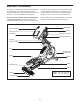
IMPORTANT PRECAUTIONS WARNING: To reduce the risk of burns, fire, electric shock, or injury to persons, read all important precautions and instructions in this manual and all warnings on your elliptical before using your elliptical. ICON assumes no responsibility for personal injury or property damage sustained by or through the use of this product. 1. It is the responsibility of the owner to ensure that all users of the elliptical are adequately informed of all precautions. 12.
STANDARD SERVICE PLANS all 5
BEFORE YOU BEGIN Thank you for selecting the revolutionary PROFORM® 1110 E elliptical. The 1110 E elliptical provides an impressive selection of features designed to make your workouts at home more effective and enjoyable. manual. To help us assist you, note the product model number and serial number before contacting us. The model number and the location of the serial number decal are shown on the front cover of this manual. For your benefit, read this manual carefully before you use the elliptical.
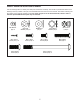
PART IDENTIFICATION CHART Use the drawings below to identify the small parts needed for assembly. The number in parentheses below each drawing is the key number of the part, from the PART LIST near the end of this manual. The number following the key number is the quantity needed for assembly. Note: If a part is not in the hardware kit, check to see if it has been preassembled. Extra parts may be included.
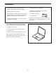
ASSEMBLY • To hire an authorized service technician to assemble this product, call 1-800-445-2480. • To identify small parts, see page 7. • In addition to the included tool(s), assembly requires the following tools: • Assembly requires two persons. • Place all parts in a cleared area and remove the packing materials. Do not dispose of the packing materials until you nish all assembly steps.
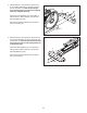
2. With the help of a second person, place some of the packing materials (not shown) under the front of the Frame (1). Have the second person hold the Frame to prevent it from tipping while you complete this step. 2 6 105 Attach the Front Stabilizer (6) to the Frame (1) with two M10 x 122mm Screws (104) and two M10 Split Washers (105). Remove the packing materials from under the front of the Frame (1). 1 3.
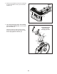
4. Press the Cover Mounts (106) on the underside of the Rear Stabilizer Cover (15) into the Rear Stabilizer (2). 4 15 2 106 5. Tip: Avoid pinching the wires. Avoid damaging the indicated plastic tabs. Set the Upright (4) on the Frame (1). 5 Avoid pinching the wires and avoid damaging the tabs Attach the Upright (4) with four M10 x 25mm Screws (99) and four M10 Split Washers (105). Do not fully tighten the Screws yet.
6. See the inset drawing. Locate the wire tie in the lower end of the Upright (4). Tie the wire tie to the Upper Wire (110) and to the Fan Extension Wire (146). Then, pull the upper end of the wire tie until the Upper Wire and the Fan Extension Wire are routed through the Upright. 6 Wire Tie 146 110 Tip: To prevent the wires from falling into the Upright (4), secure the wires with the wire tie. 146 110 Wire Tie 4 110 7.
8. Identify the Right Upper Body Arm (61) and orient it as shown. 8 Slide the Right Upper Body Arm (61) onto the Right Upper Body Leg (60). Attach the Right Upper Body Arm (61) with two M8 x 38mm Bolts (96) and two M8 Locknuts (102). Make sure that the Locknuts are in the hexagonal holes. 47 Hexagonal Holes Repeat this step for the Left Upper Body Arm (47). 60 102 61 9. Untie and discard the wire tie on the Upper Wire (110) and the Fan Extension Wire (146).
10. Tip: Avoid pinching the wires. Attach the Console (7) to the Upright (4) with four M4 x 16mm Screws (101). 10 7 Avoid pinching the wires 101 4 101 11. Orient the Right Pedal Arm (58) assembly as shown. 11 Apply grease to the axle on the Right Pedal Arm (58). Attach the Right Pedal Arm (58) to the Right Roller Arm (59) with an M8 x 13mm Screw (82), a Small Axle Cover (55), and an M8 Washer (97). Tip: Avoid damaging the Small Axle Cover when tightening the Screw.
12. Apply grease to a Pedal Arm Axle (64). 12 Next, slide an M8 Washer (97) and an Axle Spacer (77) onto an M8 x 13mm Screw (82), and tighten the Screw a few turns into the Pedal Arm Axle (64). While a second person holds the front end of the Right Pedal Arm (58) inside the bracket on the Right Upper Body Leg (60), insert the Pedal Arm Axle (64) into both parts.
14. Orient the Shield Cover Cap (118) as shown. 14 Attach the Shield Cover Cap (118) around the Upright (4) by pressing it into the Shield Cover (75). 4 118 75 15. Orient the Rear Console Cover (80) as shown. 15 Attach the Rear Console Cover (80) to the Upright (4) with two M4 x 16mm Screws (101). 79 Orient the Front Console Cover (79) as shown. Attach the Front Console Cover (79) around the Upright (4) by pressing it into the Rear Console Cover (80).
. Orient the Rear Upright Cover (81) as shown. 16 117 Attach the Rear Upright Cover (81) to the Upright (4) with four M4 x 16mm Screws (101). Orient the Front Upright Cover (117) as shown. Attach the Front Upright Cover (117) around the Upright (4) by pressing it into the Rear Upright Cover (81). 101 81 17. Identify the Right Upper Body Arm Front Cover (65) and orient it as shown.
18. Identify the Right Upper Body Leg Inner Cover (83) and orient it as shown. 18 Attach the Right Upper Body Leg Inner Cover (83) to the Right Upper Body Leg (60) with an M4 x 16mm Screw (101) and an M5 Washer (94). Identify the Right Upper Body Leg Outer Cover (69) and orient it as shown. 60 83 Attach the Right Upper Body Leg Outer Cover (69) around the Right Upper Body Leg (60) by pressing it into the Right Upper Body Leg Inner Cover (83).
THE CHEST HEART RATE MONITOR HOW TO PUT ON THE HEART RATE MONITOR The heart rate monitor consists of a chest strap and a sensor. Insert the tab on one end of the chest strap into the hole in one end of the sensor as shown. Then, press the end of the sensor under the buckle on the chest strap. The tab should be flush with the front of the sensor.
HOW TO USE THE ELLIPTICAL HOW TO PLUG IN THE POWER CORD A temporary adapter may be used to connect the power cord to a 2-pole receptacle as shown at the right if a properly grounded outlet is not available. This product must be grounded. If it should malfunction or break down, grounding provides a path of least resistance for electric current to reduce the risk of electric shock. The power cord has a plug with a grounding pin.
HOW TO MOVE THE ELLIPTICAL HOW TO ADJUST THE POSITIONS OF THE PEDALS Due to the size and weight of the elliptical, moving it requires two persons. Stand in front of the elliptical, hold the upright, and place one foot against one of the wheels. Pull on the upright and have a second person lift the rear stabilizer until the elliptical will roll on the wheels. Carefully move the elliptical to the desired location, and then lower it to the floor. Each pedal can be adjusted to several positions.
HOW TO EXERCISE ON THE ELLIPTICAL To dismount the elliptical, wait until the pedals come to a complete stop. Note: The elliptical does not have a free wheel; the pedals will continue to move until the flywheel stops. When the pedals are stationary, step off the higher pedal first. Then, step off the lower pedal. To mount the elliptical, hold the handlebars or the upper body arms and step onto the pedal that is in the lower position. Then, step onto the other pedal.
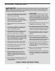
CONSOLE DIAGRAM MAKE YOUR FITNESS GOALS A REALITY WITH IFIT.COM Upload your workout results to the iFit cloud and track your accomplishments. With your new iFit-compatible fitness equipment, you can use an array of features on iFit.com to make your fitness goals a reality: Set calorie, time, or distance goals for your workouts. Exercise anywhere in the world with customizable Google Maps. Choose and download sets of weight-loss workouts.
FEATURES OF THE CONSOLE HOW TO TURN ON THE POWER The advanced console offers an array of features designed to make your workouts more effective and enjoyable. IMPORTANT: If the elliptical has been exposed to cold temperatures, allow it to warm to room temperature before turning on the power. If you do not do this, you may damage the console displays or other electrical components. The console features revolutionary iFit technology that enables the console to communicate with your wireless network.
HOW TO SET UP THE CONSOLE HOW TO USE THE MANUAL MODE Before using the elliptical for the first time, set up the console. 1. Begin pedaling or press any button on the console to turn on the console. 1. Create an iFit account. See HOW TO TURN ON THE POWER on page 23. To create an iFit account, or for more information about the account, go to www.iFit.com and click Join iFit. 2. Select the manual mode. The manual mode will be selected automatically each time you turn on the console. The iFit.
4. Follow your progress with the display. Time—When the manual mode is selected, this display mode will show the elapsed time. The display can show the following workout information: The matrix offers several display tabs. Press the Display button repeatedly until the desired tab is shown. You can also press the increase and decrease buttons next to the Enter button. Incline—This tab will show a prole of the incline settings of the workout.
When a wireless iFit module is connected, the wireless symbol at the top of the display will show the strength of your wireless signal. Four arcs indicate full signal strength. When your pulse is detected, one or two dashes will appear, and then your heart rate will be shown. For the most accurate heart rate reading, hold the contacts for at least 15 seconds. If the display does not show your heart rate, make sure that your hands are positioned as described.
HOW TO USE AN ONBOARD WORKOUT As you exercise, you will be prompted to keep your pedaling speed near the target rpm for the current segment. When an upward-pointing arrow appears in the display, increase your pace. When a downward-pointing arrow appears, decrease your pace. When no arrow appears, maintain your current pace. 1. Begin pedaling or press any button on the console to turn on the console. See HOW TO TURN ON THE POWER on page 23. 2. Select an onboard workout.
HOW TO USE A SET-A-GOAL WORKOUT Note: The calorie goal is an estimate of the number of calories that you will burn during the workout. The actual number of calories that you burn will depend on various factors such as your weight. In addition, if you manually change the resistance or incline of the ramp during the workout, the number of calories you burn will be affected. 1. Begin pedaling or press any button on the console to turn on the console. See HOW TO TURN ON THE POWER on page 23. 2.
HOW TO USE AN IFIT WORKOUT will burn during the workout and a profile of the resistance settings of the workout. Note: To use an iFit workout, the console must be connected to a wireless network (see page 30). An iFit account is also required (see step 1 on page 24). Note: The calorie goal is an estimate of the number of calories that you will burn during the workout. The actual number of calories that you burn will depend on various factors such as your weight.
HOW TO CHANGE CONSOLE SETTINGS iFit User Setup—To set up a different iFit account, but maintain the existing wireless connection, follow the instructions in the matrix. Note: This option will be used rarely. The console features a settings mode that allows you to view usage information, to personalize console settings, and to set up and manage a wireless network connection. Firmware Update—For the best results, regularly check for firmware updates. 1. Select the settings mode.
Clear WiFi—To erase the console’s wireless network settings and have it forget the currently selected wireless network, follow the instructions in the matrix. the caps option, the number option, or the symbol option. Press the up, down, left, and right buttons to highlight the desired letter or number. Then, press the Enter button to select the letter, number, or symbol. When you have finished entering the password, press the Done button.
Then, cycle the power of the elliptical: press the power switch on the elliptical to the off position, wait for several seconds, and then press the power switch to the reset position. Note: It may take a few minutes for the console to be ready for use. computer, smart phone, tablet, or other Wi-Fi device. Next, type in the IP address on the console into the URL bar in your browser. Example: http://192.168.0.1:8080. Your browser will load a web page.
MAINTENANCE AND TROUBLESHOOTING Inspect and tighten all parts of the elliptical regularly. Replace any worn parts immediately. HOW TO CALIBRATE THE RAMP If the ramp is not functioning properly, the ramp may need to be calibrated. To calibrate the ramp, press and hold the fan decrease button for several seconds until the test mode appears in the display. To clean the elliptical, use a damp cloth and a small amount of mild soap.
EXERCISE GUIDELINES Burning Fat—To burn fat effectively, you must exercise at a low intensity level for a sustained period of time. During the first few minutes of exercise, your body uses carbohydrate calories for energy. Only after the first few minutes of exercise does your body begin to use stored fat calories for energy. If your goal is to burn fat, adjust the intensity of your exercise until your heart rate is near the lowest number in your training zone.
PART LIST Key No. Qty. 1 2 3 4 5 6 7 8 9 10 11 12 13 14 15 16 17 18 19 20 21 22 23 24 25 26 27 28 29 30 31 32 33 34 35 36 37 38 39 40 41 42 43 44 45 46 47 48 49 50 1 1 1 1 8 1 1 1 1 1 1 1 1 1 1 2 2 1 1 2 4 1 1 1 1 1 4 1 1 2 1 1 2 2 1 2 1 1 1 2 1 1 2 1 1 1 1 1 1 8 Model No. PFEL10112.0 R0113A Description Key No. Qty.
Key No. Qty. 101 102 103 104 105 106 107 108 109 110 111 112 113 114 115 116 117 118 119 120 121 122 123 124 125 126 127 128 129 27 10 12 4 8 9 1 8 2 1 1 1 1 4 1 2 1 1 1 1 6 1 1 2 2 2 2 1 1 Description Key No. Qty.
106 104 33 3 105 114 121 121 21 21 15 121 16 10 33 92 114 21 84 23 2 106 121 101 108 121 17 120 12 48 11 84 21 20 71 148 84 29 92 14 26 122 102 24 22 17 13 27 50 38 39 101 115 141 28 142 113 41 25 93 109 112 50 124 125 85 86 148 126 43 32 101 43 82 30 123 90 40 1 88 89 91 50 101 102 50 42 40 126 101 86 85 78 127 31 127 78 71 18 124 125 50 105 19 6 34 108 20 101 30 109 34 104 EXPLODED DRAWING A Model No.
143 103 129 131 133 95 76 132 47 130 95 82 53 70 50 102 103 128 96 101 62 97 68 97 77 56 97 82 97 55 53 82 55 51 100 67 82 98 97 95 77 45 98 57 100 51 94 46 56 44 57 64 101 101 82 49 103 50 56 138 95 133 145 53 56 72 57 57 97 59 131 66 100 57 53 95 83 130 103 82 101 60 132 97 57 95 87 58 77 100 97 97 65 61 57 82 77 57 64 82 97 101 69 94 102 96 101 52 EXPLODED DRAWING B Model No. PFEL10112.
116 7 5 147 5 107 101 37 148 5 81 8 5 96 39 73 5 144 36 80 54 102 99 101 75 105 101 79 36 4 54 101 101 99 93 134 118 105 35 102 117 137 93 96 9 139 5 146 140 137 136 101 139 140 135 96 63 5 74 119 111 110 5 116 EXPLODED DRAWING C Model No. PFEL10112.
ORDERING REPLACEMENT PARTS To order replacement parts, please see the front cover of this manual.