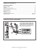
www.proform.com Model No. PFTL99108.2 Serial No. Write the serial number in the space above for reference. Serial Number Decal QUESTIONS? If you have questions, or if parts are damaged or missing, DO NOT CONTACT THE STORE; please contact Customer Care. IMPORTANT: Please register this product (see the limited warranty on the back cover of this manual) before contacting Customer Care. 1-888-533-1333 CALL TOLL-FREE: Mon.–Fri. 6 a.m.–6 p.m. MT Sat. 8 a.m.–4 p.m. MT ON THE WEB: www.proformservice.
TABLE OF CONTENTS WARNING DECAL PLACEMENT . . . . . . . . . . . . . . . . . . . . . . . . . . . . . . . . . . . . . . . . . . . . . . . . . . . . . . . . . . . . . .2 IMPORTANT PRECAUTIONS . . . . . . . . . . . . . . . . . . . . . . . . . . . . . . . . . . . . . . . . . . . . . . . . . . . . . . . . . . . . . . . . .3 BEFORE YOU BEGIN . . . . . . . . . . . . . . . . . . . . . . . . . . . . . . . . . . . . . . . . . . . . . . . . . . . . . . . . . . . . . . . . . . . . . . .5 ASSEMBLY . . . . . . . . . . .
IMPORTANT PRECAUTIONS WARNING: To reduce the risk of serious injury, read all important precautions and instructions in this manual and all warnings on your treadmill before using your treadmill. ICON assumes no responsibility for personal injury or property damage sustained by or through the use of this product. 1. Before beginning any exercise program, consult your physician. This is especially important for persons over age 35 or persons with pre-existing health problems. carrying 15 or more amps.
24. Inspect and properly tighten all parts of the treadmill regularly. 20. Never leave the treadmill unattended while it is running. Always remove the key, unplug the power cord, and switch the reset/off circuit breaker to the off position when the treadmill is not in use. (See the drawing on page 5 for the location of the circuit breaker.) 25. 21. Do not attempt to raise, lower, or move the treadmill until it is properly assembled.
BEFORE YOU BEGIN Thank you for selecting the revolutionary PROFORM® 1280 PREMIER ES treadmill. The 1280 PREMIER ES treadmill offers an impressive selection of features designed to make your workouts at home more enjoyable and effective. And when youʼre not exercising, the unique treadmill can be folded up, requiring less than half the floor space of other treadmills. ing this manual, please see the front cover of this manual.
ASSEMBLY To hire an authorized service technician to assemble the treadmill, call 1-800-445-2480. Assembly requires two persons. Set the treadmill in a cleared area and remove all packing materials. Do not dispose of the packing materials until assembly is completed. Note: The underside of the treadmill walking belt is coated with high-performance lubricant. During shipping, some lubricant may be transferred to the top of the walking belt or the shipping carton.
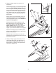
2. Identify the Right Upright (74) and the Left Upright (73). 2 Hold the Right Upright (74) near the Right Base Cover (77). See the inset drawing. Make sure that the long tie is extending from the rectangular hole in the Right Upright. Tie the long tie securely around the end of the Upright Wire (75). Then, pull the other end of the long tie until the Upright Wire is routed completely through the Right Upright.
4. Have a second person hold the console assembly near the Uprights (73, 74). 4 Connect the Upright Wire (75) to the Console Wire Harness (71). See the inset drawing. The connectors should slide together easily and snap into place. If they do not, turn one connector and try again. IF THE CONNECTORS ARE NOT CONNECTED PROPERLY, THE CONSOLE MAY BE DAMAGED WHEN THE POWER IS TURNED ON. Console Assembly 73 Remove the long tie from the Upright Wire (75). 75 5.
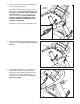
7. Slide the Right Upright Sleeve (96) up against the console assembly. Attach the Right Upright Sleeve with a #8 x 3/4" Screw (4) and a #8 x 3/4" Tek Screw (84) as shown. 7 Attach the Left Upright Sleeve (not shown) to the console assembly as described above. 4 Console Assembly 96 84 8. With the help of a second person, raise the front of the treadmill and insert the crossbar on the Base (83) into the cutout in the cardboard stand as shown.
If you purchase the optional chest pulse sensor (see page 15), follow the steps below to install the receiver included with the chest pulse sensor. 1. Make sure that the power cord is unplugged. Remove the indicated #8 x 3/4" Screws (4) from the Pulse Receiver Cover (70) on the back of the console assembly. 1 Console Assembly 70 4 2. Next, hold the receiver so the antenna is oriented as shown. Attach the receiver to the Pulse Receiver Cover (70) with the two included small screws. 3.
OPERATION AND ADJUSTMENT THE PRE-LUBRICATED WALKING BELT tric shock. This product is equipped with a cord having an equipment-grounding conductor and a grounding plug. Plug the power cord into a surge suppressor, and plug the surge suppressor into an appropriate outlet that is properly installed and grounded in accordance with all local codes and ordinances. IMPORTANT: The treadmill is not compatible with GFCI-equipped outlets. Your treadmill features a walking belt coated with highperformance lubricant.
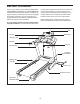
CONSOLE DIAGRAM Key Clip FEATURES OF THE CONSOLE to accept iFit interactive workout cards containing workouts designed to help you achieve specific fitness goals. For example, lose unwanted pounds with the 8week Weight Loss workout. iFit workouts automatically control the treadmill while the voice of a personal trainer coaches you through every step of your workout. iFit cards are available separately. To purchase iFit cards at any time, please see the front cover of this manual or go to www.iFit.com.
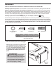
HOW TO TURN ON THE POWER IMPORTANT: If the treadmill has been exposed to cold temperatures, allow it to warm to room temperature before turning on the power. If you do not do this, you may damage the console displays or other electrical components. Plug in the power cord (see page 11). Next, locate the reset/off circuit breaker on the treadmill frame near the power cord. Make sure that the circuit breaker is in the “reset” position.
HOW TO USE THE MANUAL MODE the incline buttons numbered 0 to 12. Each time you press one of the buttons, the incline will gradually change until it reaches the selected incline setting. 1. Insert the key into the console. See HOW TO TURN ON THE POWER on page 13. When the key is inserted, the incline will automatically calibrate, tones will sound, and then the console will be ready for use. 2. Personalize console settings if desired. 6.
To measure your heart rate, stand on the foot rails and hold the metal contacts on the handrail— avoid moving your hands. When your pulse is detected, your heart rate will be shown. For the most accurate heart rate reading, continue to hold the contacts for about 15 seconds. Regardless of which display mode you select, the speed or incline setting will appear in the display for a few seconds each time you change the setting.
HOW TO USE A PRESET WORKOUT At the end of the first one-minute segment of the workout, a series of tones will sound. If a different speed and/or incline setting is programmed for the second segment, the speed setting and/or incline setting will appear in the display for a moment to alert you. The treadmill will then automatically adjust to the speed and incline settings for the second segment. 1. Insert the key into the console. See HOW TO TURN ON THE POWER on page 13. 2.
HOW TO CREATE A CUSTOM WORKOUT To program a speed setting and an incline setting for the first one-minute segment of the workout, simply adjust the speed and incline of the treadmill as desired by pressing the Speed and Incline buttons. 1. Insert the key into the console. See HOW TO TURN ON THE POWER on page 13. When the first segment ends, a series of tones will sound and the current speed and incline settings will be saved in memory. 2. Personalize console settings if desired.
HOW TO USE A CUSTOM WORKOUT speed and/or incline setting is programmed for the second segment, the speed and/or incline setting will appear in the display for a moment to alert you. The treadmill will then automatically adjust to the speed and incline settings for the second segment. 1. Insert the key into the console. See HOW TO TURN ON THE POWER on page 13. The workout will continue in this way until the small arrow reaches the right end of the profile. The walking belt will then slow to a stop. 2.
HOW TO USE AN IFIT CARD the volume for your personal trainer (see HOW TO PERSONALIZE CONSOLE SETTINGS on page 13). 1. Insert the key into the console. See HOW TO TURN ON THE POWER on page 13. If the speed or incline setting for the current segment is too high or too low, you can override the setting by pressing the speed or incline buttons; however, when the next segment begins, the treadmill will automatically adjust to the speed and incline settings for the next segment. 2.
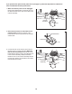
HOW TO FOLD AND MOVE THE TREADMILL HOW TO FOLD THE TREADMILL FOR STORAGE Before folding the treadmill, adjust the incline to the lowest position. If you do not do this, you may damage the treadmill when you fold it. Remove the key and unplug the power cord. CAUTION: You must be able to safely lift 45 lbs. (20 kg) to raise, lower, or move the treadmill. 1 1. Hold the metal frame firmly in the location shown by the arrow at the right.
TROUBLESHOOTING Most treadmill problems can be solved by following the steps below. Find the symptom that applies, and follow the steps listed. If further assistance is needed, please see the front cover of this manual. PROBLEM: The power does not turn on SOLUTION: a. Make sure that the power cord is plugged into a surge suppressor, and that the surge suppressor is plugged into a properly grounded outlet (see page 11).
Lower the treadmill (see HOW TO LOWER THE TREADMILL FOR USE on page 20). Remove the four indicated #8 x 3/4" Screws (4), and remove the Motor Hood (44). 4 44 Next, locate the Reed Switch (20) and the Magnet (12) on the left side of the Pulley (11). Turn the Pulley until the Magnet is aligned with the Reed Switch. Make sure that the gap between the Magnet and the Reed Switch is about 1/8 in. (3 mm).
PROBLEM: The walking belt is off-center or slips when walked on SOLUTION: a. If the walking belt is off-center, remove the key and UNPLUG THE POWER CORD. If the walking belt has shifted to the left, use the hex key to turn the left idler roller bolt clockwise 1/2 of a turn; if the walking belt has shifted to the right, turn the left idler roller bolt counterclockwise 1/2 of a turn. Be careful not to overtighten the walking belt.
EXERCISE GUIDELINES WARNING: Before beginning any exercise program, consult your physician. This is especially important for persons over age 35 or persons with pre-existing health problems. The pulse sensor is not a medical device. Various factors may affect the accuracy of heart rate readings. The pulse sensor is intended only as an exercise aid in determining heart rate trends in general. These guidelines will help you to plan your exercise program.
PART LIST—Model No. PFTL99108.2 To locate the parts listed below, see the EXPLODED DRAWING near the end of this manual. Key No. Qty. 1 2 3 4 5 6 7 8 9 10 11 12 13 14 15 16 17 18 19 20 21 22 23 24 25 26 27 28 29 30 31 32 33 34 35 36 37 38 39 40 41 42 43 44 45 46 47 48 49 50 2 2 8 50 4 1 2 4 2 2 1 1 17 1 2 2 2 2 2 1 2 1 1 1 1 1 1 1 9 2 1 2 4 1 1 1 1 10 1 1 1 2 1 1 4 2 1 1 1 1 Description Key No. Qty.
Key No. Qty. 101 102 103 104 105 1 2 4 1 2 Description Key No. Qty. Latch Warning Decal 1/2" Console Ground Screw #8 x 1" Screw Speaker Cover Idler Roller Washer 106 107 108 * * 1 1 1 – – Description Incline/Controller Wire Incline Stop Bracket Stop Bracket Spacer 4" White Wire, M/F Userʼs Manual Note: Specifications are subject to change without notice. See the back cover of this manual for information about ordering replacement parts. *These parts are not illustrated.
56 27 4 105 62 101 61 52 38 58 59 56 105 4 29 72 60 6 61 62 7 48 8 4 47 9 4 57 4 18 10 4 52 72 54 12 11 14 29 16 17 20 19 55 15 30 29 29 51 38 33 10 98 34 41 8 32 36 13 4 7 4 43 69 13 49 18 69 33 55 29 19 68 16 17 30 4 46 9 69 15 4 33 55 35 EXPLODED DRAWING A—Model No. PFTL99108.
EXPLODED DRAWING B—Model No. PFTL99108.
EXPLODED DRAWING C—Model No. PFTL99108.
EXPLODED DRAWING D—Model No. PFTL99108.
EXPLODED DRAWING E—Model No. PFTL99108.
ORDERING REPLACEMENT PARTS To order replacement parts, please see the front cover of this manual.