Model No. 831.21257.0 Serial No. Write the serial number in the space above for reference. Serial Number Decal • Assembly • Operation • Maintenance • Part List and Drawing Sears, Roebuck and Co. Hoffman Estates, IL 60179 CAUTION Read all precautions and instructions in this manual before using this equipment. Keep this manual for future reference.
TABLE OF CONTENTS WARNING DECAL PLACEMENT . . . . . . . . . . . . . . . . . . . . . . . . . . . . . . . . . . . . . . . . . . . . . . . . . . . . . . . . . . . . . . .2 IMPORTANT PRECAUTIONS . . . . . . . . . . . . . . . . . . . . . . . . . . . . . . . . . . . . . . . . . . . . . . . . . . . . . . . . . . . . . . . . . . 3 BEFORE YOU BEGIN. . . . . . . . . . . . . . . . . . . . . . . . . . . . . . . . . . . . . . . . . . . . . . . . . . . . . . . . . . . . . . . . . . . . . . . .
IMPORTANT PRECAUTIONS WARNING: To reduce the risk of serious injury, read all important precautions and instructions in this manual and all warnings on your dual trainer before using your dual trainer. Sears assumes no responsibility for personal injury or property damage sustained by or through the use of this product. 1. It is the responsibility of the owner to ensure that all users of the dual trainer are adequately informed of all precautions. 8.
BEFORE YOU BEGIN Thank you for selecting the new PROFORM® DUAL TRAINER BIKE/ROWER. Cycling and rowing are effective exercises for increasing cardiovascular fitness, building endurance, and toning the body. The DUAL TRAINER BIKE/ROWER is designed to let you enjoy these effective exercises in the convenience and privacy of your home. reading this manual, please see the back cover of this manual. To help us assist you, note the product model number and serial number before contacting us.
PART IDENTIFICATION CHART Use the drawings below to identify the small parts needed for assembly. The number in parentheses below each drawing is the key number of the part, from the PART LIST near the end of this manual. The number following the key number is the quantity needed for assembly. Note: If a part is not in the hardware kit, check to see if it has been preassembled. Extra parts may be included. If a part is missing, please call 1-888-533-1333.
ASSEMBLY • Assembly requires two persons. • In addition to the included tool(s), assembly requires the following tools: • Place all parts in a cleared area and remove the packing materials. Do not dispose of the packing materials until you finish all assembly steps. one Phillips screwdriver one adjustable wrench • To identify small parts, see page 5. Assembly may be easier if you have a set of wrenches. To avoid damaging parts, do not use power tools.
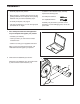
3. Orient the Rear Stabilizer (3) as indicated by the sticker; make sure that the welded tubes are on the side shown. 3 Attach the Rear Stabilizer (3) to the Rear Frame (18) with two M10 x 100mm Screws (13). 3 18 13 4. Orient the Rail Collar (6) as shown, and slide it onto the Rail Pivot Bracket (96). Welded Tube 4 See the lower drawing. Orient the Rail (5) as shown, and slide it onto the Rail Pivot Bracket (96).
5. Tip: It may be helpful to have a second person raise and hold the Rail (5) and the Rear Frame (18) while you do this step. 5 5 Attach the Rail Bracket (8) to the underside of the Rail (5) with four M8 x 20mm Screws (15); start all the Screws, and then tighten them. 8 See step 4. Tighten the M8 x 20mm Screws (15). 15 6. Orient the Seat Carriage (4) as shown.
8. Locate the four M6 x 13mm Screws (95) in the lower end of the Backrest Frame (94). Insert the heads of the Screws into the slotted holes in the Seat Carriage (4), and then slide the Screws downward into the slots. 8 94 95 4 9. Pull the Foot Plate Knob (49), raise the Foot Plate (68) to the position shown in the inset drawing, and then release the Foot Plate Knob into the indicated hole in the Front Frame (1).
. Identify the Right Pedal (11). 10 Using an adjustable wrench, firmly tighten the Right Pedal (11) clockwise into the Right Crank Arm (86). Firmly tighten the Left Pedal (10) counterclockwise into the Left Crank Arm (not shown). IMPORTANT: You must turn the Left Pedal counterclockwise to attach it. 10 11 86 11. Attach the Row Bar (12) to the Strap (59) with the Row Bar Clip (100).
12. The Console (30) can use four AA batteries (not included); alkaline batteries are recommended. Do not use old and new batteries together or alkaline, standard, and rechargeable batteries together. IMPORTANT: If the Console has been exposed to cold temperatures, allow it to warm to room temperature before you insert batteries. Otherwise, you may damage the console displays or other electronic components.
HOW TO USE THE DUAL TRAINER HOW TO MOVE THE DUAL TRAINER HOW TO SET UP THE RECUMBENT MODE Stand behind the dual trainer and lift the rail cap until the dual trainer will roll on the wheels. Carefully move the dual trainer to the desired location, and then lower it to the floor. Follow the instructions below to set up the dual trainer in the Recumbent mode. 3 4 2 1 1. Remove the row bar. Remove the row bar from the row bar clip on the strap (see assembly step 11 on page 10).
HOW TO SET UP THE ROWER MODE Note: If the front of dual trainer lifts off the floor while you are exercising with the dual trainer set up in the Rower mode, first turn the Leveling leveling foot Foot beneath the rear frame so that it is tight against Leveling the rear frame. Feet Then, turn both of the leveling feet beneath the rear stabilizer until the lifting motion is eliminated. Follow the instructions below to set up the dual trainer in the Rower mode.
HOW TO FOLD AND STORE THE DUAL TRAINER 1. Raise the foot plate. Pull the foot plate knob, raise the foot plate, and then release the foot plate knob into the hole in the front frame (see assembly step 9 on page 9). IMPORTANT: The foot plate must be raised when you fold the dual trainer, or damage may occur to the foot plate. The dual trainer can be stored in a folded position to conserve space. Store the dual trainer in a location where children cannot tip it.
CONSOLE DIAGRAM FEATURES OF THE CONSOLE The console offers a selection of features designed to make your dual trainer recumbent and rower workouts more effective and enjoyable. Manual Mode—When you use the dual trainer in the Recumbent mode, you can change the resistance of the pedals with the touch of a button. When you use the dual trainer in the Rower mode, you can change the resistance of the row bar with the touch of a button.
HOW TO USE THE MANUAL MODE Time—This display shows the elapsed time. Note: When a workout is selected, the display shows the time remaining in the workout instead of the elapsed time. 1. Turn on the console. To turn on the console, press the On/Reset button or begin pedaling or rowing. The entire display will turn on for a moment; the console will then be ready for use. Distance (Dist.
As you exercise, the upper section of the display will alternately show the elapsed time and the distance that you have pedaled or rowed; the lower-left section of the display will alternately show the number of calories you have burned and your power output in watts. The lower-right section of the display will show your pedaling or rowing speed. To select the scan mode again, press the Display button repeatedly until the word SCAN appears in the display.
HOW TO USE A SMART WORKOUT If the resistance level for the current segment is too high or too low, you can manually override the setting by pressing the Resistance buttons. IMPORTANT: When the current segment of the workout ends, the pedals or the row bar will automatically adjust to the resistance level programmed for the next segment. 1. Turn on the console. To turn on the console, press the On/Reset button or begin pedaling or rowing.
THE USER MODE The display will show the selected unit of measurement. An E for English miles or an M for metric kilometers will appear in the display. To change the unit of measurement, press the Display button repeatedly. The console features a user mode that allows you to select a unit of measurement for the dual trainer. To select the user mode, press and hold down the Recumbent Performance button for a few seconds until the user mode information appears in the display.
MAINTENANCE AND TROUBLESHOOTING MAINTENANCE Locate the left-side Reed Switch (22). Turn the Left Crank Arm (85) until a Magnet (109) is aligned with the Reed Switch. Loosen, but do not remove, the #8 x 12mm Flange Screw (28). Inspect and tighten all parts of the dual trainer regularly. Replace any worn parts immediately. To clean the dual trainer, use a damp cloth and a small amount of mild detergent.
HOW TO ADJUST THE RIGHT-SIDE REED SWITCHES HOW TO ADJUST THE DRIVE BELT If the console does not display correct feedback when the dual trainer is in the Rower mode, the right-side reed switches should be adjusted. If you can feel the pedals slip while you are pedaling when the dual trainer is set up in the Recumbent mode, even when the resistance is at the highest level, the drive belt may need to be adjusted.
EXERCISE GUIDELINES Aerobic Exercise—If your goal is to strengthen your cardiovascular system, you must perform aerobic exercise, which is activity that requires large amounts of oxygen for prolonged periods of time. For aerobic exercise, adjust the intensity of your exercise until your heart rate is near the highest number in your training zone. WARNING: Before beginning this or any exercise program, consult your physician.
SUGGESTED STRETCHES The correct form for several basic stretches is shown at the right. Move slowly as you stretch; never bounce. 1. Toe Touch Stretch Stand with your knees bent slightly and slowly bend forward from your hips. Allow your back and shoulders to relax as you reach down toward your toes as far as possible. Hold for 15 counts, then relax. Repeat 3 times. Stretches: Hamstrings, back of knees and back. 1 2. Hamstring Stretch Sit with one leg extended.
PART LIST Key No. Qty. 1 2 3 4 5 6 7 8 9 10 11 12 13 14 15 16 17 18 19 20 21 22 23 24 25 26 27 28 29 30 31 32 33 34 35 36 37 38 39 40 41 42 43 44 45 46 47 48 49 50 1 1 1 1 1 1 1 1 1 1 1 1 4 2 12 1 1 1 1 1 1 1 2 2 4 1 1 7 1 1 1 1 1 17 1 1 5 1 3 1 1 4 4 2 2 2 2 10 1 1 Model No. 831.21257.0 R0714A Description Key No. Qty.
Key No. Qty. 101 102 103 104 105 106 107 108 109 1 2 1 1 1 2 2 2 6 Description Key No. Qty. Shield Cover Plate #8 x 12mm Screw Shield Cover Motor Bracket Console Bracket #8 x 25mm Screw M6 Locknut Foot Frame Cap Magnet 110 111 112 113 114 115 * * * 2 1 1 1 2 1 – – – Description Leveling Foot Spacer Lock Knob E-clip Handlebar M8 Curved Washer M10 Bolt Set User’s Manual Assembly Tool PTFE Grease Packet Note: Specifications are subject to change without notice.
EXPLODED DRAWING A Model No. 831.21257.
EXPLODED DRAWING B 88 58 59 Model No. 831.21257.
1 YEAR FULL WARRANTY If this Sears Dual Trainer Exerciser fails due to a defect in material or workmanship within 1 year of the date of purchase, call 1-800-4-MY-HOME® (1-800-469-4663) to arrange for free repair (or replacement if repair proves impossible). The frame is warranted for a lifetime. This warranty does not apply when the Dual Trainer Exerciser is used commercially or for rental purposes.