www.proform.com Model No. PFEX03908.0 Serial No. Write the serial number in the space above for reference. Serial Number Decal QUESTIONS? As a manufacturer, we are committed to providing complete customer satisfaction. If you have questions, or if parts are missing, DO NOT CONTACT THE STORE; please contact Customer Care. IMPORTANT: You must note the product model number and serial number (see the drawing above) before contacting us: 1-888-533-1333 CALL TOLL-FREE: Mon.–Fri., 6 a.m.–6 p.m. MT Sat.
TABLE OF CONTENTS WARNING DECAL PLACEMENT . . . . . . . . . . . . . . . . . . . . . . . . . . . . . . . . . . . . . . . . . . . . . . . . . . . . . . . . . . . . . .2 IMPORTANT PRECAUTIONS . . . . . . . . . . . . . . . . . . . . . . . . . . . . . . . . . . . . . . . . . . . . . . . . . . . . . . . . . . . . . . . .3 BEFORE YOU BEGIN . . . . . . . . . . . . . . . . . . . . . . . . . . . . . . . . . . . . . . . . . . . . . . . . . . . . . . . . . . . . . . . . . . . . . .4 ASSEMBLY . . . . . . . . . . . . .
IMPORTANT PRECAUTIONS WARNING: To reduce the risk of serious injury, read all important precautions and instructions in this manual and all warnings on your exercise cycle before using your exercise cycle. ICON assumes no responsibility for personal injury or property damage sustained by or through the use of this product. 8. The pulse sensor is not a medical device. Various factors, including the user's movement, may affect the accuracy of heart rate readings.
BEFORE YOU BEGIN Thank you for selecting the revolutionary PROFORM® 280 RE exercise cycle. Cycling is an effective exercise for increasing cardiovascular fitness, building endurance, and toning the body. The 280 RE exercise cycle provides an impressive selection of features designed to make your workouts at home more effective and enjoyable. after reading this manual, please see the FRONT cover of this manual. To help us assist you, note the product model number and serial number before contacting us.
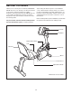
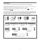
ASSEMBLY To hire an authorized service technician to assemble the exercise cycle, call 1-800-445-2480. Assembly requires two persons. Place all parts of the exercise cycle in a cleared area and remove the packing materials. Do not dispose of the packing materials until assembly is completed. In addition to the included tool(s), assembly requires a Phillips screwdriver adjustable wrench . and an As you assemble the exercise cycle, use the drawings below to identify small parts.
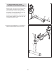
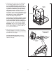
1. 1 To make assembly easier, read the information on page 5 before you begin. With the help of another person, lift the Frame (1) and place a packing insert (not shown) under the Frame. Have the other person hold the Frame to prevent it from moving from side to side until you complete this step. 3 Attach the Front Stabilizer (3) to the Frame (1) with two M10 x 80mm Patch Screws (47) and two M10 Split Washers (48). 1 2.
3. Identify the Right and Left Stabilizer Covers (12, 13), which are marked with “R” and “L” stickers. 3 Attach each Stabilizer Cover (12, 13) to the Rear Stabilizer (2) with two M4 x 16mm Screws (62). 62 62 13 2 62 12 62 4. Identify the Top Shield (14) and the Upright (4). 4 With the help of another person, slide the Top Shield (14) upward onto the Upright (4). Make sure that the Top Shield and the Upright are oriented as shown.
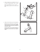
5. Have another person hold the Upright (4) and the Top Shield (14) near the Frame (1). Locate the wire tie in the Upright and the Wire Harness (40) in the Frame. 5 Avoid pinching the Wire Harness (40) 54 See the inset drawing. Tie the wire tie to one of the connectors on the Wire Harness (40). Then, pull the other end of the wire tie upward out of the top of the Upright (4). Discard the wire tie. 54 14 54 4 Tip: Avoid pinching the Wire Harness (40). Slide the Upright (4) onto the Frame (1).
7. The Console (5) can use four 1.5V D batteries (not included); alkaline batteries are recommended. IMPORTANT: If the Console has been exposed to cold temperatures, allow it to warm to room temperature before inserting batteries. Otherwise, you may damage the console displays or other electronic components. Remove the battery cover, insert the batteries into the battery compartments, and reattach the battery cover. Make sure to orient the batteries as shown by the diagram inside the battery compartments.
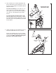
9. Tip: Avoid pinching the Pulse Wire. Orient the Pulse Bar (7) as shown. Attach the Pulse Bar to the Seat Carriage (6) with two M10 x 36mm Screws (57) and two M10 Locknuts (58). Do not tighten the Screws yet. 9 Avoid pinching the Pulse Wire 7 Pulse Wire 58 6 57 57 10. Tip: Avoid pinching the Pulse Wire (not shown). Attach the Backrest (8) to the Seat Carriage (6) with two M6 x 18mm Patch Screws (59) and two M6 x 42mm Patch Screws (60). 10 59 8 See step 9. Tighten the M10 x 36mm Screws (57).
. Orient the Seat (9) as shown. Attach the Seat to the Seat Carriage (6) with four 1/4" x 38mm Patch Screws (61) and four M6 Washers (63). Note: The Patch Screws and the Washers may be preattached to the underside of the Seat. 11 9 6 63 61 12. Attach the Pulse Bar Cover (15) to the Seat Carriage (6) with two M4 x 16mm Screws (62).
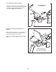
13. Plug the Pulse Wire into the Pulse Receptacle (39) in the Frame (1). 13 Pulse Wire 39 14. Identify the Right Pedal (44), which is marked with an “R.” Using an adjustable wrench, firmly tighten the Right Pedal (44) clockwise into the right side of the Crank (17). Tighten the Left Pedal (not shown) counterclockwise into the left side of the Crank. 1 14 IMPORTANT: Tighten both pedals as firmly as possible. After using the exercise cycle for one week, retighten the pedals.
HOW TO USE THE EXERCISE CYCLE HOW TO ADJUST THE PEDAL STRAPS To adjust the pedal straps, first pull the ends of the straps off the tabs on the pedals. Adjust the straps to the desired position, and then press the ends of the straps onto the tabs. HOW TO MOVE THE EXERCISE CYCLE To move the exercise cycle, lift the rear stabilizer until the exercise cycle can be moved on the front wheels. Carefully move the exercise cycle to the desired location and then lower it to the floor.
CONSOLE DIAGRAM FEATURES OF THE CONSOLE automatically control the resistance of the pedals and prompt you to vary your pedaling pace while counting down the calories you burn. The advanced console offers an array of features designed to make your workouts more effective and enjoyable. When you select the manual mode of the console, you can change the resistance of the pedals with a touch of the dial. As you exercise, the console will provide continuous exercise feedback.
HOW TO USE THE MANUAL MODE The third section of the display will show the approximate number of calories you have burned and the resistance level of the pedals. The display will change modes every few seconds. The display will also show your heart rate when you use the handgrip pulse sensor (see step 5 below). 1. Turn on the console. To turn on the console, press any button or begin pedaling. The display will light and the console will be ready for use. 2. Select the manual mode.
HOW TO USE A TRAINER WORKOUT As you exercise, the display will prompt you to keep your pedaling pace near the pace setting for the current segment. When the word “faster” appears in the display, increase your pace. When the word “slower” appears, decrease your pace. When the center of the target flashes, maintain your current pace. 1. Turn on the console. To turn on the console, press any button or begin pedaling. The display will light and the console will be ready for use. 2. Select a trainer workout.
HOW TO USE A CALORIE GOAL WORKOUT As you exercise, the display will prompt you to keep your pedaling pace near the pace setting for the current segment. When the word “faster” appears in the display, increase your pace. When the word “slower” appears, decrease your pace. When the center of the target flashes, maintain your current pace. 1. Turn on the console. To turn on the console, press any button or begin pedaling. The display will light and the console will be ready for use. 2.
HOW TO USE AN IFIT WORKOUT THE INFORMATION MODE iFit cards are available separately. To purchase iFit cards, go to www.iFit.com or see the front cover of this manual. iFit cards are also available at select stores. The console features an information mode that allows you to select a unit of measurement for the console and to view usage information for the exercise cycle. 1. Turn on the console. To select the information mode, press and hold down the Workout button for a few seconds.
MAINTENANCE AND TROUBLESHOOTING HOW TO ADJUST THE DRIVE BELT Inspect and tighten all parts of the exercise cycle regularly. Replace any worn parts immediately. If you can feel the pedals slip while you are pedaling, even when the resistance is at the highest level, the drive belt may need to be adjusted. To clean the exercise cycle, use a damp cloth and a small amount of mild soap. IMPORTANT: To avoid damage to the console, keep liquids away from the console and keep the console out of direct sunlight.
EXERCISE GUIDELINES WARNING: Burning Fat—To burn fat effectively, you must exercise at a low intensity level for a sustained period of time. During the first few minutes of exercise, your body uses carbohydrate calories for energy. Only after the first few minutes of exercise does your body begin to use stored fat calories for energy. If your goal is to burn fat, adjust the intensity of your exercise until your heart rate is near the lowest number in your training zone.
PART LIST—Model No. PFEX03908.0 Key No. Qty. 1 2 3 4 5 6 7 8 9 10 11 12 13 14 15 16 17 18 19 20 21 22 23 24 25 26 27 28 29 30 31 32 33 34 35 36 37 1 1 1 1 1 1 1 1 1 1 1 1 1 1 1 1 1 1 1 1 1 1 1 1 1 1 1 1 1 2 2 2 2 4 2 4 4 Description Key No. Qty.
72 7 64 72 62 57 64 57 35 36 63 63 53 63 64 58 37 61 33 32 58 63 64 34 34 6 63 63 72 64 72 9 64 31 63 53 72 27 63 35 70 72 26 36 37 8 59 25 40 60 29 59 60 56 30 15 5 39 55 54 4 14 54 56 54 62 54 28 30 55 EXPLODED DRAWING A—Model No. PFEX03908.
62 62 42 13 62 62 45 52 2 62 45 42 62 43 11 38 51 58 16 65 62 12 62 62 43 66 22 1 49 20 21 62 69 41 71 18 68 46 19 50 21 24 67 23 50 62 3 62 62 17 41 48 46 62 47 10 44 44 EXPLODED DRAWING B—Model No. PFEX03908.
ORDERING REPLACEMENT PARTS To order replacement parts, please see the front cover of this manual.