www.proform.com Model No. PFEX63910.1 Serial No. Write the serial number in the space above for reference. Serial Number Decal QUESTIONS? If you have questions, or if parts are damaged or missing, DO NOT CONTACT THE STORE; please contact Customer Care. IMPORTANT: Please register this product (see the limited warranty on the back cover of this manual) before contacting Customer Care. 1-888-533-1333 CALL TOLL-FREE: Mon.–Fri., 6 a.m.–6 p.m. MT Sat. 8 a.m.–4 p.m. MT ON THE WEB: www.proformservice.
TABLE OF CONTENTS WARNING DECAL PLACEMENT . . . . . . . . . . . . . . . . . . . . . . . . . . . . . . . . . . . . . . . . . . . . . . . . . . . . . . . . . . . . . .2 IMPORTANT PRECAUTIONS . . . . . . . . . . . . . . . . . . . . . . . . . . . . . . . . . . . . . . . . . . . . . . . . . . . . . . . . . . . . . . . .3 BEFORE YOU BEGIN . . . . . . . . . . . . . . . . . . . . . . . . . . . . . . . . . . . . . . . . . . . . . . . . . . . . . . . . . . . . . . . . . . . . . .4 PART IDENTIFICATION CHART . . . . .
IMPORTANT PRECAUTIONS WARNING: To reduce the risk of serious injury, read all important precautions and instructions in this manual and all warnings on your exercise bike before using your exercise bike. ICON assumes no responsibility for personal injury or property damage sustained by or through the use of this product. 1. Before beginning any exercise program, consult your physician. This is especially important for persons over age 35 or persons with pre-existing health problems. 8.
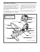
BEFORE YOU BEGIN Thank you for selecting the revolutionary PROFORM® 300 CR exercise bike. Cycling is an effective exercise for increasing cardiovascular fitness, building endurance, and toning the body. The 300 CR exercise bike provides an impressive selection of features designed to make your workouts at home more effective and enjoyable. after reading this manual, please see the front cover of this manual. To help us assist you, note the product model number and serial number before contacting us.
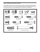
PART IDENTIFICATION CHART See the drawings below to identify the small parts needed for assembly. The number in parentheses below each drawing is the key number of the part, from the PART LIST near the end of this manual. The number following the key number is the quantity needed for assembly. Note: If a part is not in the hardware kit, check to see if it has been preassembled. To avoid damaging parts, do not use power tools for assembly.
ASSEMBLY • To hire an authorized service technician to assemble the exercise bike, call 1-800-445-2480. • To identify small parts, see page 5. • In addition to the included tool(s), assembly requires the following tools: • Assembly requires two persons. one adjustable wrench • Place all parts in a cleared area and remove the packing materials. Do not dispose of the packing materials until you complete all assembly steps.
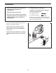
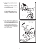
2. While another person lifts the rear of the Frame (1), attach the Rear Stabilizer (16) to the Frame with four M8 x 55mm Patch Screws (52) and four M8 Split Washers (55). 2 1 16 55 55 52 3. While another person holds the Upright (2) near the Frame (1), locate the wire tie in the Upright. 3 See the inset drawing. Tie the lower end of the wire tie to the Pulse Extension Wire (79) and to the Main Wire Harness (43). Next, pull the other end of the wire tie upward out of the top of the Upright (2).
4. Identify the Right and Left Handlebars (59, 60), which are marked with “Right” and “Left” stickers. 4 Orient the Right and Left Handlebars (59, 60) so that the hexagonal holes are in the indicated locations. 60 61 Attach each Handlebar (59, 60) to the Upright (2) with two M8 x 38mm Button Bolts (72) and two M8 Locknuts (61). Make sure that the Locknuts are in the hexagonal holes. Hexagonal Holes 72 5. The Console (4) can use four 1.
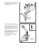
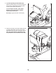
6. Untie and discard the wire ties on the Main Wire Harness (43) and the Pulse Extension Wire (79). 6 While another person holds the Console (4) near the Upright (2), connect the wires on the Console to the Main Wire Harness (43) and to the Pulse Extension Wire (79). 4 79 Insert the excess wire into the Upright (2) or into the Console (4). 2 80 80 43 Tip: Avoid pinching the wires. Attach the Console (4) to the Upright (2) with four M4 x 16mm Flange Screws (80). Avoid pinching the wires 7.
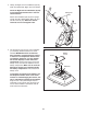
8. Tip: Avoid pinching the Pulse Wire (58). Attach the Backrest (8) to the Seat Carriage (3) with two M6 x 18mm Patch Screws (77) and two M6 x 42mm Patch Screws (51). 8 51 8 Tip: First tighten the M6 x 18mm Patch Screws (77), and then tighten the M6 x 42mm Patch Screws (51). See step 7. Tighten the M10 Locknuts (64). 3 58 9. Attach the Seat (9) to the Seat Carriage (3) with four M6 x 38mm Patch Screws (81) and four M6 Washers (44) (only two of each are shown).
10. Plug the Pulse Wire (58) into the Pulse Receptacle (79) located in the Left Shield (26). 10 79 58 26 11. Identify the Right Pedal (21), which is marked with an “R.” Using an adjustable wrench, firmly tighten the Right Pedal clockwise into the Right Crank (23). 11 Tighten the Left Pedal (not shown) counterclockwise into the Left Crank (not shown). 23 21 Strap Tab Adjust the strap on the Right Pedal (21) to the desired position, and press the ends of the strap onto the tab on the Right Pedal.
HOW TO USE THE EXERCISE BIKE HOW TO ADJUST THE UPRIGHT HOW TO ADJUST THE PEDAL STRAPS To adjust the pedal straps, first pull the ends of the straps off the tabs on the pedals. Adjust the straps to the desired position, and then press the ends of the straps onto the tabs. The upright can be adjusted to the position that is the most comfortable for you. To adjust the upright, first raise the upright so that it is not resting on the upright knob.
CONSOLE DIAGRAM FEATURES OF THE CONSOLE For example, lose unwanted pounds with the 8-week Weight Loss workout. iFit workouts control the resistance of the pedals while the voice of a personal trainer coaches you through your workouts. iFit cards are available separately. To purchase iFit cards, go to www.iFit.com or call the telephone number on the front cover of this manual. iFit cards are also available at select stores.
HOW TO USE THE MANUAL MODE The lower right display—The lower right display can show your pedaling speed in miles per hour or kilometers per hour and the approximate number of calories that you have burned. 1. Begin pedaling or press any button on the console to turn on the console. A moment after you begin pedaling or press a button, a tone will sound, and the display will turn on. 2. Select the manual mode.
HOW TO USE A PRESET WORKOUT Note: The console can show pedaling pace and distance in either miles or kilometers. To view or change the unit of measurement, see HOW TO CHANGE CONSOLE SETTINGS on page 17. 1. Begin pedaling or press any button on the console to turn on the console. 5. Measure your heart rate if desired. A moment after you begin pedaling or press a button, a tone will sound, and the display will turn on.
HOW TO USE AN IFIT WORKOUT The flashing segment of the profile represents the current segment of the workout. The height of the flashing segment indicates the resistance level for the current segment. At the end of each segment of the workout, a series of tones will sound and the next segment of the profile will begin to flash. If a different resistance level is programmed for the next segment, the resistance level will appear in the display for a few seconds to alert you.
HOW TO USE THE SOUND SYSTEM The upper display will show the currently selected backlight option. Press the Silent Magnetic Resistance increase button repeatedly to select the desired backlight option. To play music or audio books through the console sound system while you exercise, plug an audio cable (not included) into the jack on the console and into a jack on your MP3 player or CD player; make sure that the audio cable is fully plugged in. 3. Select a unit of measurement if desired.
MAINTENANCE AND TROUBLESHOOTING HOW TO ADJUST THE REED SWITCH Inspect and tighten all parts of the exercise bike regularly. Replace any worn parts immediately. If the console does not display correct feedback, the reed switch should be adjusted. To clean the exercise bike, use a damp cloth and a small amount of mild soap. IMPORTANT: To avoid damage to the console, keep liquids away from the console and keep the console out of direct sunlight.
HOW TO ADJUST THE BELT If the pedals slip while you are pedaling, even while the resistance is adjusted to the highest setting, the belt may need to be adjusted. To adjust the belt, you must first remove the right pedal and the right front shield. Using an adjustable wrench, turn the right pedal counterclockwise and remove it. 47 88 Next, remove all the screws from the left and right front shields; there are two sizes of screws in the front shields–note which size of screw you remove from each hole.
FCC INFORMATION This equipment has been tested and found to comply with the limits for a Class B digital device, pursuant to part 15 of the FCC Rules. These limits are designed to provide reasonable protection against harmful interference in a residential installation. This equipment generates, uses, and can radiate radio frequency energy and, if not installed and used in accordance with the instructions, may cause harmful interference to radio communications.
EXERCISE GUIDELINES WARNING: Before beginning this Burning Fat—To burn fat effectively, you must exercise at a low intensity level for a sustained period of time. During the first few minutes of exercise, your body uses carbohydrate calories for energy. Only after the first few minutes of exercise does your body begin to use stored fat calories for energy. If your goal is to burn fat, adjust the intensity of your exercise until your heart rate is near the lowest number in your training zone.
SUGGESTED STRETCHES The correct form for several basic stretches is shown at the right. Move slowly as you stretch—never bounce. 1. Toe Touch Stretch 1 Stand with your knees bent slightly and slowly bend forward from your hips. Allow your back and shoulders to relax as you reach down toward your toes as far as possible. Hold for 15 counts, then relax. Repeat 3 times. Stretches: Hamstrings, back of knees and back. 2. Hamstring Stretch 2 Sit with one leg extended.
NOTES 23
PART LIST Key No. Qty. 1 2 3 4 5 6 7 8 9 10 11 12 13 14 15 16 17 18 19 20 21 22 23 24 25 26 27 28 29 30 31 32 33 34 35 36 37 38 39 40 41 42 43 44 45 1 1 1 1 2 2 1 1 1 2 1 2 1 1 1 1 2 2 2 2 1 1 1 1 1 1 1 1 1 2 1 1 2 1 1 2 4 2 1 1 1 1 1 12 1 Description Key No. Qty.
Key No. Qty. 91 92 93 94 95 96 97 98 1 4 2 1 1 1 1 1 Description Key No. Qty. Resistance Motor M4 x 12mm Flange Screw M6 x 8mm Hex Screw M6 x 65mm Hex Bolt Resistance Magnet Resistance Arm Motor Disc M3.5 x 12mm Screw 99 100 101 102 103 104 * * 1 1 1 1 1 2 – – Description Resistance Bracket M5 Washer M5 x 7mm Screw M6 Locknut Small Snap Ring Adjustment Nut Assembly Tool Userʼs Manual Note: Specifications are subject to change without notice.
EXPLODED DRAWING A Model No. PFEX63910.
EXPLODED DRAWING B 8 9 44 57 81 11 64 78 5 6 57 84 77 51 10 77 Model No. PFEX63910.
ORDERING REPLACEMENT PARTS To order replacement parts, see the front cover of this manual.