Model No. 30464.0 Serial No. USER’S MANUAL Write the serial number in the space above for future reference. Serial Number Decal QUESTIONS? As a manufacturer, we are committed to providing complete customer satisfaction. If you have questions, or if parts are missing, PLEASE DO NOT CONTACT THE STORE; please contact our Customer Service Department. IMPORTANT: You must note the product model number and serial number (see the drawing above) before contacting us: CALL TOLL-FREE: 1-888-936-4266 Mon.–Fri.
TABLE OF CONTENTS WARNING DECAL PLACEMENT . . . . . . . . . . . . . . . . . . . . . . . . . . . . . . . . . . . . . . . . . . . . . . . . . . . . . . . . . . . . . .2 IMPORTANT PRECAUTIONS . . . . . . . . . . . . . . . . . . . . . . . . . . . . . . . . . . . . . . . . . . . . . . . . . . . . . . . . . . . . . . . . .3 BEFORE YOU BEGIN . . . . . . . . . . . . . . . . . . . . . . . . . . . . . . . . . . . . . . . . . . . . . . . . . . . . . . . . . . . . . . . . . . . . . . .5 ASSEMBLY . . . . . . . . . . . .
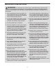
IMPORTANT PRECAUTIONS WARNING: To reduce the risk of serious injury, read all important precautions and instructions in this manual and all warnings on your treadmill before using your treadmill. ICON assumes no responsibility for personal injury or property damage sustained by or through the use of this product. (not included) and plug the surge suppressor into a grounded circuit capable of carrying 15 or more amps. No other appliance should be on the same circuit. Do not use an extension cord. 1.
20. Never leave the treadmill unattended while it is running. Always remove the key, unplug the power cord, and switch the reset/off circuit breaker to the off position when the treadmill is not in use. (See the drawing on page 5 for the location of the circuit breaker.) 25. Never drop or insert any object into any opening on the treadmill. 21. Do not attempt to raise, lower, or move the treadmill until it is properly assembled. (See ASSEMBLY on page 6 and HOW TO FOLD AND MOVE THE TREADMILL on page 18.
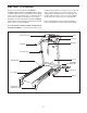
BEFORE YOU BEGIN Thank you for selecting the new PROFORM® TRAINER 420 treadmill. The TRAINER 420 treadmill combines advanced technology with innovative design to let you enjoy an excellent form of cardiovascular exercise in the convenience and privacy of your home. And when you’re not exercising, the unique TRAINER 420 treadmill can be folded up, requiring less than half the floor space of other treadmills. ing this manual, please see the front cover of this manual.
ASSEMBLY Assembly requires two persons. Set the treadmill in a cleared area and remove all packing materials. Do not dispose of the packing materials until assembly is completed. Note: The underside of the treadmill walking belt is coated with high-performance lubricant. During shipping, lubricant may be transferred to the top of the walking belt or the shipping carton. This is a normal condition and does not affect treadmill performance.
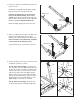
2. Have a second person hold the Base (52) in the position shown. 2 Identify the Left Upright (53) (the Right Upright [54] has a large hole near the lower end). 54 Small Holes Hold the Left Upright (53) so the two small holes for the latch assembly are on top as shown. Attach the Left Upright to the Base (52) with two M10 x 75mm Bolts (2) and two M10 Star Washers (9). Do not tighten the Bolts yet. 2 Large Hole Attach the Right Upright (54) in the same way. 52 53 9 9 2 3.
5. See the left inset drawing. Identify the two Frame Spacers (11). Open the included packet of grease, and apply grease to both sides of both Frame Spacers. Then, identify the outer side of each Frame Spacer. 5 54 Hold a Frame Spacer (11) between the Right Upright (54) and the Lift Frame (23), with the outer side of the Frame Spacer facing the Right Upright. 9 With the help of a second person, raise the front of the treadmill.
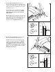
7. Set the Console Assembly (91) face down on a soft surface to avoid scratching it. Hold the Right Handrail (33), which has a large hole in one side, near the Console Assembly. 7 Console Wire 85 Tie 7 Bracket Next, insert the console wire and the tie into the hole in the side of the Right Handrail (33). Using needlenose pliers, pull the console wire out of the hole near the bracket on the Right Handrail. Large Hole 33 Then, set the Right Handrail (33) on the Console Assembly (91).
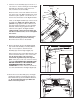
. Tighten two M8 x 15mm Bolts (8) with two M8 Star Washers (5) into the Uprights (53, 54). 10 See step 9. Tighten the M8 x 15mm Bolts (8) used in step 9. With the help of a second person, carefully lower the Uprights (53, 54) to the floor. 8 5 53 54 8 5 11. Attach the ground wire on the Wire Harness (39) to the indicated hole in the Base (52) with an M4 x 10mm Screw (84).
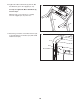
12. Lower the Uprights (53, 54). See the lower drawing. Position the Uprights so that the Frame (51) is centered between them. 12 1 53, 54 Firmly tighten the two M10 x 60mm Bolts (1) and the four M10 x 75mm Bolts (2). Be careful not to overtighten the Bolts. 2 51 Raise the Uprights (53, 54). Top View 54 13. Attach the Latch Housing (48) to the Left Upright (53) with two M4.2 x 19mm Screws (10); start both Screws before tightening either of them.
OPERATION AND ADJUSTMENT THE PRE-LUBRICATED WALKING BELT Your treadmill features a walking belt coated with highperformance lubricant. IMPORTANT: Never apply silicone spray or other substances to the walking belt or the walking platform. Such substances will deteriorate the walking belt and cause excessive wear. HOW TO PLUG IN THE POWER CORD DANGER: Improper connection of the equipment-grounding conductor can result in an increased risk of electric shock.
CONSOLE DIAGRAM Key Clip To turn on the power, follow the steps beginning on page 14. To use the manual mode of the console, see page 14. To use a preset workout, see page 16. To use the stereo sound system, see page 17. To use the information mode, see page 17. FEATURES OF THE CONSOLE The treadmill console offers a selection of features designed to make your workouts more effective.
HOW TO TURN ON THE POWER HOW TO USE THE MANUAL MODE IMPORTANT: If the treadmill has been exposed to cold temperatures, allow it to warm to room temperature before turning on the power. If you do not do this, the console displays or other electrical components may become damaged. 1. Insert the key into the console. Plug in the power cord (see page 12). Next, locate the reset/off circuit breaker on the treadmill frame near the power cord. Switch the circuit breaker to the reset position.
5. Follow your progress with the track and the displays. 6. Measure your heart rate if desired. Before using the handgrip pulse sensor, remove the sheets of clear plastic from the metal contacts. In addition, make sure that your hands are clean. The track—The track represents a distance of 1/4 mile (400 meters). As you walk or run on the treadmill, the indicators around the track will appear in succession until the entire track appears.
HOW TO USE A PRESET WORKOUT the next segment, the speed or incline setting will flash in the display to alert you. 1. Insert the key into the console. The workout will continue in this way until the last segment of the profile flashes in the display and the last segment ends. The walking belt will then slow to a stop. See HOW TO TURN ON THE POWER on page 14. 2. Select one of the four preset workouts.
HOW TO USE THE STEREO SOUND SYSTEM THE INFORMATION MODE To play music or audio books through the console’s stereo speakers, you must connect your MP3 player, CD player, or other personal audio player to the console. Locate the audio wire below the display on the console, and plug it into a jack on your MP3 player, CD player, or other personal audio player. Make sure that the audio wire is fully plugged in.
HOW TO FOLD AND MOVE THE TREADMILL HOW TO FOLD THE TREADMILL FOR STORAGE 1 Before folding the treadmill, adjust the incline to the lowest position. If you do not do this, the treadmill may be permanently damaged. Next, unplug the power cord. CAUTION: You must be able to safely lift 45 lbs. (20 kg) to raise, lower, or move the treadmill. 1. Hold the metal frame firmly in the location shown by the arrow at the right.
TROUBLESHOOTING Most treadmill problems can be solved by following the steps below. Find the symptom that applies, and follow the steps listed. If further assistance is needed, see the front cover of this manual. PROBLEM: The power does not turn on SOLUTION: a. Make sure that the power cord is plugged into a surge suppressor, and that the surge suppressor is plugged into a properly grounded outlet (see page 12).
Locate the Reed Switch (89) and the Magnet (62) on the left side of the Pulley (71). Turn the Pulley until the Magnet is aligned with the Reed Switch. Make sure that the gap between the Magnet and the Reed Switch is about 1/8 in. (3 mm). If necessary, loosen the M4.2 x 13mm Tek Screw (3), move the Reed Switch slightly, and then retighten the Screw. Reattach the Hood (not shown), and run the treadmill for a few minutes to check for a correct speed reading. 1/8 in.
EXERCISE GUIDELINES Burning Fat—To burn fat effectively, you must exercise at a low intensity level for a sustained period of time. During the first few minutes of exercise, your body uses carbohydrate calories for energy. Only after the first few minutes of exercise does your body begin to use stored fat calories for energy. If your goal is to burn fat, adjust the intensity of your exercise until your heart rate is near the lowest number in your training zone.
PART LIST—Model No. 30464.0 Key No. Qty. 1 2 3 4 5 6 7 8 9 10 11 12 13 14 15 16 17 18 19 20 21 22 23 24 25 26 27 28 29 30 31 32 33 34 35 36 37 38 39 40 41 42 43 44 45 46 47 48 49 50 2 4 2 13 6 1 2 6 6 16 4 1 4 2 1 4 1 1 4 3 7 1 1 1 6 6 2 4 2 2 1 4 1 2 2 2 1 2 1 1 4 4 4 6 2 1 3 1 2 2 Description R1207A Key No. Qty. M10 x 60mm Bolt M10 x 75mm Bolt M4.2 x 13mm Tek Screw M4.2 x 16mm Screw M8 Star Washer English Latch Warning Decal M5 Star Washer M8 x 15mm Bolt M10 Star Washer M4.
Key No. Qty. 101 102 103 104 105 106 107 108 109 2 3 1 2 2 2 2 2 1 Description Front Roller Washer M4.2 x 18mm Screw Console Fan M10 x 58mm Bolt Cage Nut Caution Decal Isolator M4 x 10mm Controller Screw Audio Wire Key No. Qty. Description 1 French Latch Warning Decal 110 111 1 Warning Decal * – 6" Red Wire, M/F * – 8" Black Wire, M/F – 4" Blue Wire, 2F * * – 16" Blue Wire, 2F * – User’s Manual *These parts are not illustrated. Specifications are subject to change without notice.
29 75 24 36 21 42 60 27 10 19 107 74 44 6 102 25 29 36 21 42 75 78 97 55 50 67 10 25 10 61 19 4 64 44 44 27 25 93 25 110 51 68 11 86 28 16 25 19 107 76 102 83 41 62 89 71 3 78 101 95 10 56 28 94 50 19 25 41 46 16 17 81 44 11 18 96 101 41 93 31 95 41 EXPLODED DRAWING A—Model No. 30464.
EXPLODED DRAWING B—Model No. 30464.
EXPLODED DRAWING C—Model No. 30464.
EXPLODED DRAWING D—Model No. 30464.
ORDERING REPLACEMENT PARTS To order replacement parts, please see the front cover of this manual.