www.proform.com Model No. PFEX63912.1 Serial No. Write the serial number in the space above for reference. Serial Number Decal ACTIVATE YOUR WARRANTY To register your product and activate your warranty today, go to www.proformservice.com/ registration. CUSTOMER CARE For service at any time, go to www.proformservice.com. Or call 1-888-533-1333 Mon.–Fri. 6 a.m.–6 p.m. MT Sat. 8 a.m.–4 p.m. MT Please do not contact the store.
TABLE OF CONTENTS WARNING DECAL PLACEMENT . . . . . . . . . . . . . . . . . . . . . . . . . . . . . . . . . . . . . . . . . . . . . . . . . . . . . . . . . . . . . . . 2 IMPORTANT PRECAUTIONS . . . . . . . . . . . . . . . . . . . . . . . . . . . . . . . . . . . . . . . . . . . . . . . . . . . . . . . . . . . . . . . . . . 3 BEFORE YOU BEGIN. . . . . . . . . . . . . . . . . . . . . . . . . . . . . . . . . . . . . . . . . . . . . . . . . . . . . . . . . . . . . . . . . . . . . . . .
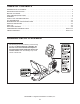
IMPORTANT PRECAUTIONS WARNING: To reduce the risk of serious injury, read all important precautions and instructions in this manual and all warnings on your exercise bike before using your exercise bike. ICON assumes no responsibility for personal injury or property damage sustained by or through the use of this product. 1. It is the responsibility of the owner to ensure that all users of the exercise bike are adequately informed of all precautions. 8.
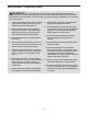
STANDARD SERVICE PLANS all 4
BEFORE YOU BEGIN Thank you for selecting the revolutionary PROFORM® 320 CX exercise bike. Cycling is an effective exercise for increasing cardiovascular tness, building endurance, and toning the body. The 320 CX exercise bike provides an impressive selection of features designed to make your workouts at home more effective and enjoyable. reading this manual, please see the front cover of this manual. To help us assist you, note the product model number and serial number before contacting us.
PART IDENTIFICATION CHART Use the drawings below to identify the small parts needed for assembly. The number in parentheses below each drawing is the key number of the part, from the PART LIST near the end of this manual. The number following the key number is the quantity needed for assembly. Note: If a part is not in the hardware kit, check to see if it has been preassembled. Extra parts may be included.
ASSEMBLY • To hire an authorized service technician to assemble this product, call 1-800-445-2480. • To identify small parts, see page 6. • In addition to the included tool(s), assembly requires the following tools: • Assembly requires two persons. • Place all parts in a cleared area and remove the packing materials. Do not dispose of the packing materials until you nish all assembly steps.
3. While another person lifts the rear of the Frame (1), attach the Rear Stabilizer (3) to the Frame with two M10 x 95mm Screws (62). 3 3 1 62 4. Slide the Shield Cover (5) upward onto the Upright (4). 4 5 Avoid pinching the wires Have a second person hold the Shield Cover (5) around the Upright (4) until you complete step 4. 4 Tip: Avoid pinching the wires inside the Frame (1). Slide the Upright (4) onto the Frame.
5. Locate the wire tie inside the Upright (4). Then, locate the Main Wire (89) and the Frame Pulse Wire (30) inside the Frame (1). 5 5 Wire Tie Tie the lower end of the wire tie to the ends of the Main Wire (89) and the Frame Pulse Wire (30). Wire Tie 30 89 4 Then, pull the other end of the wire tie upward until the Main Wire (89) and the Frame Pulse Wire (30) are routed completely through the Upright (4).
7. Insert the Main Wire (89) and the Frame Pulse Wire (30) upward through the indicated hole in the Handlebar (6). 7 6 30 89 8. While another person holds the Console (7) near the Handlebar (6), connect the wires on the Console to the Main Wire (89) and the Frame Pulse Wire (30). 8 6 7 79 30 Insert the excess wire downward into the Upright (4) or upward into the Console (7). Tip: Avoid pinching the wires. Attach the Console (7) to the Handlebar (6) with four M4 x 16mm Screws (79).
10. Attach the Seat (15) to the Seat Carriage (11) with four M6 x 50mm Screws (65) and four M6 Washers (66) (only two of each are shown). Note: The Screws and Washers may be preattached to the underside of the Seat. 10 15 11 66 66 65 11. Attach the Backrest (13) to the Seat Carriage (11) with five M8 x 16mm Screws (60) and five M8 Split Washers (61). 11 Tip: It may be helpful to adjust the seat during this step. See HOW TO ADJUST THE SEAT on page 14.
. Identify and orient the Pulse Bar (12) so that the Pulse Grips (41) face upward. 12 Avoid pinching the Pulse Wire (29) Tip: Avoid pinching the Pulse Wire (29). While a second person holds the Pulse Bar (12), attach the Pulse Bar to the Seat Carriage (11) with two M8 x 45mm Screws (63) and two M8 Split Washers (61). 41 11 Tip: It may be helpful to adjust the seat during this step. See HOW TO ADJUST THE SEAT on page 14. 41 12 61 63 29 13.
14. Identify the Right Pedal (16). 14 Using an adjustable wrench, firmly tighten the Right Pedal (16) clockwise into the Right Crank Arm (17). Firmly tighten the Left Pedal (not shown) counterclockwise into the Left Crank Arm (not shown). Adjust the right strap to the desired position, and press the ends of the strap onto the tabs on the Right Pedal (16). Adjust the strap on the Left Pedal (not shown) in the same way. 17 Strap 16 Tab 15.
HOW TO USE THE EXERCISE BIKE HOW TO PLUG IN THE POWER ADAPTER HOW TO ADJUST THE PEDAL STRAPS IMPORTANT: If the exercise bike has been exposed to cold temperatures, allow it to warm to room temperature before plugging in the power adapter. If you do not do this, you may damage the console displays or other electronic components. To adjust the pedal straps, first pull the ends of the straps off the tabs on the pedals.
HOW TO MOVE THE EXERCISE BIKE HOW TO LEVEL THE EXERCISE BIKE To move the exercise bike, hold the handle on the rear stabilizer and carefully lift it until the exercise bike can be moved on the front wheels. Carefully move the exercise bike to the desired location and then lower it. If the exercise bike rocks slightly on your floor during use, turn one or both of the leveling knobs on the rear stabilizer and adjust the leveling feet until the rocking motion is eliminated.
CONSOLE DIAGRAM FEATURES OF THE CONSOLE The advanced console offers an array of features designed to make your workouts more effective and enjoyable. When you use the manual mode of the console, you can change the resistance of the pedals with the touch of a button. While you exercise, the console will display continuous exercise feedback. You can also measure your heart rate using the handgrip heart rate monitor. Lose unwanted pounds with the progressive 8-week weight-loss program.
HOW TO ACTIVATE THE CONSOLE 4. Follow your progress with the display. The included power adapter must be used to operate the exercise bike. See HOW TO PLUG IN THE POWER ADAPTER on page 14. When the power adapter is plugged in, the displays will turn on and the console will be ready for use. The center left display—This display can show the elapsed time and the distance in miles or kilometers that you have pedaled.
5. Measure your heart rate if desired. If the display does not show your heart rate, make sure that your hands are positioned as described. Be careful not to move your hands excessively or to squeeze the contacts tightly. For optimal performance, clean the contacts using a soft cloth; never use alcohol, abrasives, or chemicals to clean the contacts. If there are sheets of plastic on the metal contacts Contacts on the handgrip heart rate monitor, remove the plastic.
HOW TO USE AN 8-WEEK WEIGHT-LOSS WORKOUT the profile will begin to flash. If a different resistance level and/or target speed is programmed for the next segment, the resistance level will appear in the display for a few seconds to alert you. The resistance of the pedals will then change. 1. Begin pedaling or press any button on the console to turn on the console. See HOW TO ACTIVATE THE CONSOLE on page 17.
HOW TO USE A PRESET WORKOUT As you exercise, you will be prompted to keep your pedaling speed near the target speed for the current segment. When an upward-pointing arrow appears in the lower display, increase your pedaling speed. When a downward-pointing arrow appears, decrease your pedaling speed. When no arrow appears, maintain your current pedaling speed. 1. Begin pedaling or press any button on the console to turn on the console. See HOW TO ACTIVATE THE CONSOLE on page 17. 2. Select a preset workout.
HOW TO USE THE SOUND SYSTEM The console has three backlight options. The ON option keeps the backlight on while the console is on. The AUTO option keeps the backlight on only while you are pedaling. The OFF option turns off the backlight. To play music or audio books through the console sound system while you exercise, plug a 3.5 mm male to 3.
FCC INFORMATION This equipment has been tested and found to comply with the limits for a Class B digital device, pursuant to part 15 of the FCC Rules. These limits are designed to provide reasonable protection against harmful interference in a residential installation. This equipment generates, uses, and can radiate radio frequency energy and, if not installed and used in accordance with the instructions, may cause harmful interference to radio communications.
MAINTENANCE AND TROUBLESHOOTING Inspect and tighten all parts of the exercise bike regularly. Replace any worn parts immediately. Repeat these actions until the console displays correct feedback. When the reed switch is correctly adjusted, reattach the shield cover. To clean the exercise bike, use a damp cloth and a small amount of mild soap. IMPORTANT: To avoid damage to the console, keep liquids away from the console and keep the console out of direct sunlight.
EXERCISE GUIDELINES Burning Fat—To burn fat effectively, you must exercise at a low intensity level for a sustained period of time. During the first few minutes of exercise, your body uses carbohydrate calories for energy. Only after the first few minutes of exercise does your body begin to use stored fat calories for energy. If your goal is to burn fat, adjust the intensity of your exercise until your heart rate is near the lowest number in your training zone.
PART LIST Key No. Qty. 1 2 3 4 5 6 7 8 9 10 11 12 13 14 15 16 17 18 19 20 21 22 23 24 25 26 27 28 29 30 31 32 33 34 35 36 37 38 39 40 41 42 43 44 45 46 47 48 49 50 51 1 1 1 1 1 1 1 1 1 1 1 1 1 1 1 1 1 1 1 1 1 1 1 1 4 1 1 2 1 1 4 1 1 1 1 1 1 4 2 2 2 2 2 2 1 1 1 1 1 2 1 Model No. PFEX63912.1 R0713A Description Key No. Qty.
55 40 38 55 55 63 39 66 69 55 66 60 69 61 61 12 66 40 38 61 37 39 76 41 7 55 38 55 66 28 66 66 55 83 62 55 95 69 55 66 33 82 85 11 69 85 53 68 70 3 76 41 67 62 88 31 35 29 18 32 6 96 86 68 36 93 19 95 88 48 97 64 4 61 72 88 91 28 30 1 86 43 5 52 43 8 88 51 79 88 31 27 20 81 50 74 61 52 44 88 61 52 77 56 78 90 84 88 60 45 61 46 80 47 93 44 60 9 61 71 79 92 88 31 52 60 61 67 61 60 70 60 71 72 59
88 88 87 87 88 88 24 14 25 88 25 88 10 27 23 88 66 88 13 88 65 75 65 66 15 88 57 75 22 75 88 88 21 49 88 EXPLODED DRAWING B Model No. PFEX63912.
ORDERING REPLACEMENT PARTS To order replacement parts, please see the front cover of this manual.