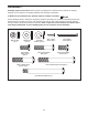
Model No. 30331.1 Serial No. Write the serial number in the space above for reference. USERʼS MANUAL Serial Number Decal QUESTIONS? If you have questions, or if parts are damaged or missing, PLEASE CONTACT OUR CUSTOMER SERVICE DEPARTMENT DIRECTLY. 1-888-936-4266 CALL TOLL-FREE: Mon.–Fri., 7:30 until 16:30 ET (excluding holidays) OR E-MAIL US: customerservice@iconcanada.ca CAUTION Read all precautions and instructions in this manual before using this equipment.
TABLE OF CONTENTS WARNING DECAL PLACEMENT . . . . . . . . . . . . . . . . . . . . . . . . . . . . . . . . . . . . . . . . . . . . . . . . . . . . . . . . . . . . . .2 IMPORTANT PRECAUTIONS . . . . . . . . . . . . . . . . . . . . . . . . . . . . . . . . . . . . . . . . . . . . . . . . . . . . . . . . . . . . . . . .3 BEFORE YOU BEGIN . . . . . . . . . . . . . . . . . . . . . . . . . . . . . . . . . . . . . . . . . . . . . . . . . . . . . . . . . . . . . . . . . . . . . .4 ASSEMBLY . . . . . . . . . . . . .
IMPORTANT PRECAUTIONS WARNING: To reduce the risk of serious injury, read all important precautions and instructions in this manual and all warnings on your elliptical before using your elliptical. ICON assumes no responsibility for personal injury or property damage sustained by or through the use of this product. 1. Before beginning any exercise program, consult your physician. This is especially important for persons over age 35 or persons with pre-existing health problems. 9.
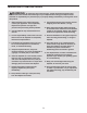
BEFORE YOU BEGIN Thank you for purchasing the PROFORM® 390 E elliptical. The 390 E elliptical provides an array of features designed to make your workouts at home more effective and enjoyable. manual. To help us assist you, note the product model number and serial number before contacting us. The model number and the location of the serial number decal are shown on the front cover of this manual. For your benefit, read this manual carefully before you use the elliptical.
ASSEMBLY Assembly requires two persons. Place all parts of the elliptical in a cleared area and remove the packing materials. Do not dispose of the packing materials until assembly is completed. In addition to the included tool(s), assembly requires a Phillips screwdriver . See the drawings below to identify the small parts needed for assembly. The number in parentheses below each drawing is the key number of the part, from the PART LIST near the end of this manual.
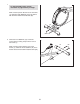
1. 1 To make assembly easier, read the information on page 5 before you begin. While a second person lifts the rear of the Frame (1), attach the Rear Stabilizer (70) to the Frame with two M10 x 85mm Patch Screws (82). 70 1 82 2. Orient the Front Stabilizer (73) so that the “Front” sticker is facing away from the front of the Frame (1). 2 73 While a second person lifts the front of the Frame (1), attach the Front Stabilizer (73) to the Frame with two M10 x 85mm Patch Screws (82).
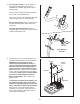
3. Orient the Upright (2) and the Top Shield Cover (37) as shown. Slide the Top Shield Cover upward onto the Upright. 3 Have a second person hold the Upright (2) near the Frame (1). Wire Tie See the inset drawing. Locate the wire tie in the Upright (2). Tie the lower end of the wire tie to the Wire Harness (42). Next, pull the upper end of the wire tie upward out of the top of the Upright.
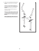
5. See the upper drawing. To avoid pinching or damaging the Pulse Wires (28) while you assemble the Handlebar (39), perform the following actions: 5 Insert the end of the left Pulse Wire (28) inside the left side of the Handlebar (39). 39 Then, insert the end of the right Pulse Wire (28) inside the right side of the Handlebar (39). See the lower drawing. Have a second person hold the Handlebar (39) in place around the Upright (2). 28 Tip: Avoid pinching the wires.
7. Untie and discard the wire tie attached to the Wire Harness (42). 7 Locate the Pulse Wires (28) inside the left and right sides of the Handlebar (39) and pull them upward out of the Upright (2). 4 42 While a second person holds the Console (4) near the Upright (2), connect wires on the Console to the Wire Harness (42) and to the Pulse Wires (28). 28 Insert the excess wires into the Upright (2). Tip: Avoid pinching the wires.
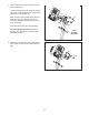
9. Identify the Left and Right Upper Body Arms (8, 9), which are marked with “Left” and “Right” stickers. 9 Orient the Left Upper Body Arm (8) and an Upper Body Leg (6) as shown. Make sure that the hexagonal holes are in the indicated location. Insert the Left Upper Body Arm (8) into the Upper Body Leg (6). 8 Attach the Left Upper Body Arm (8) with two M8 x 45mm Button Bolts (76) and two M8 Jam Nuts (77). Make sure that the Jam Nuts are in the hexagonal holes. Do not tighten the Button Bolts yet.
10. Apply a generous amount of the included grease to the axles on the Upright (2). Orient the Left and Right Upper Body Arms (8, 9) as shown, and slide them onto the left and right sides of the Upright (2). 10 8 Attach each Upper Body Arm (8, 9) with an M8 x 20mm Patch Screw (80) and an M8 Washer (33). 80 33 2 9 Grease 11. Apply a small amount of grease to a Shoulder Patch Bolt (31).
. See the inset drawing. Identify a Pivot Cover A (19), which has hooks, and a Pivot Cover B (22), which has tabs. 12 Press a Pivot Cover A (19) and a Pivot Cover B (22) together around the Right Upper Body Arm (9). Repeat this step for the other side of the elliptical. 8 Tabs Tip: Make sure that the Pivot Covers (19, 22) are positioned as shown. 22 Hooks 22 Hooks Orient the Front Upright Cover (16) so that the indicated arrow is pointing upward. 22 19 19 13.
14. Press a Front Leg Cover (20) and a Rear Leg Cover (21) together around the right Upper Body Leg (6). 14 6 Repeat this step for the other side of the elliptical. 20 21 15. Identify the Right Pedal (13), which is marked with a “Right” sticker. Attach the Right Pedal (13) to the Right Pedal Arm (49) with three M10 x 48mm Patch Screws (75) and three M10 Split Washers (78). Make sure to use the center hole and the two outer holes to attach the Right Pedal.
16. Press the Rear Shield Cover (59) onto the Left and Right Shields (44, 45). 16 59 44 45 17. Make sure that all parts of the elliptical are properly tightened. Note: Some hardware may be left over after assembly is completed. To protect the floor or carpet from damage, place a mat under the elliptical.
HOW TO USE THE ELLIPTICAL HOW TO MOVE THE ELLIPTICAL HOW TO EXERCISE ON THE ELLIPTICAL Due to the size and weight of the elliptical, moving it requires two persons. Stand in front of the elliptical, hold the upright, and place one foot against one of the front wheels. Pull on the upright and have a second person lift the handle until the elliptical will roll on the wheels. Carefully move the elliptical to the desired location, and then lower it to the floor.
CONSOLE DIAGRAM FEATURES OF THE CONSOLE You can even connect your MP3 player or CD player to the console sound system and listen to your favorite music or audio books while you exercise. The advanced console offers an array of features designed to make your workouts more effective and enjoyable. To use the manual mode, see page 17. To use a preset workout, see page 18. To use the sound system, see page 18.
HOW TO USE THE MANUAL MODE 4. Follow your progress with the displays. 1. Turn on the console. The upper display—This display will show the elapsed time and the resistance level of the pedals each time the resistance level changes. Press any button or begin pedaling to turn on the console. When you turn on the console, the display will light. A tone will sound and the console will be ready for use. 2. Select the manual mode. When you turn on the console, the manual mode will be selected.
5. Measure your heart rate if desired. If your heart rate is not shown, make sure that your hands are positioned as described. Be careful not to move your hands excessively or to squeeze the metal contacts tightly. For optimal performance, clean the metal contacts using a soft cloth; never use alcohol, abrasives, or chemicals to clean the contacts. If there are sheets of plastic on the Contacts metal contacts on the handgrip pulse sensor, remove the plastic.
HOW TO USE A PRESET WORKOUT If you stop pedaling for several seconds, a series of tones will sound and the workout will pause. 1. Turn on the console. To restart the workout, simply resume pedaling. The workout will continue until the last segment of the profile flashes and the last segment of the workout ends. See step 1 on page 17. 2. Select a preset workout.
MAINTENANCE AND TROUBLESHOOTING Inspect and tighten all parts of the elliptical regularly. Replace any worn parts immediately. 44 To clean the elliptical, use a damp cloth and a small amount of mild soap. IMPORTANT: To avoid damage to the console, keep liquids away from the console and keep the console out of direct sunlight. 14 CONSOLE TROUBLESHOOTING 92 If the console displays become dim, replace all the batteries at the same time; most console problems are the result of low batteries.
HOW TO ADJUST THE REED SWITCH Locate the Reed Switch (58). Loosen, but do not remove, the M4 x 16mm Screw (92). If the console does not display correct feedback, the reed switch should be adjusted. To adjust the reed switch, you must remove the right disc cover and the right pedal disc. Using a flat screwdriver, remove the right Disc Cover (18). 27 92 81 58 18 24 41 Next, rotate the Crank Assembly (24) until a Magnet (41) is aligned with the Reed Switch (58).
EXERCISE GUIDELINES WARNING: Burning Fat—To burn fat effectively, you must exercise at a low intensity level for a sustained period of time. During the first few minutes of exercise, your body uses carbohydrate calories for energy. Only after the first few minutes of exercise does your body begin to use stored fat calories for energy. If your goal is to burn fat, adjust the intensity of your exercise until your heart rate is near the lowest number in your training zone.
SUGGESTED STRETCHES The correct form for several basic stretches is shown at the right. Move slowly as you stretch—never bounce. 1. Toe Touch Stretch 1 Stand with your knees bent slightly and slowly bend forward from your hips. Allow your back and shoulders to relax as you reach down toward your toes as far as possible. Hold for 15 counts, then relax. Repeat 3 times. Stretches: Hamstrings, back of knees and back. 2. Hamstring Stretch 2 Sit with one leg extended.
PART LIST Key No. Qty. 1 2 3 4 5 6 7 8 9 10 11 12 13 14 15 16 17 18 19 20 21 22 23 24 25 26 27 28 29 30 31 32 33 34 35 36 37 38 39 40 41 42 43 44 45 1 1 1 1 1 2 1 1 1 2 2 1 1 1 2 1 4 2 2 2 2 2 4 1 1 1 1 2 4 2 2 1 4 1 1 1 1 2 1 2 2 1 2 1 1 Description Key No. Qty.
Key No. Qty. 91 92 93 94 95 96 97 2 21 2 1 1 1 1 Description Key No. Qty. Adjustment Nut M4 x 16mm Screw Pulse Sensor/Wire Flywheel Bearing Audio Cable Left Crank Arm Crank Arm Spacer 98 99 * * * * 4 4 – – – – Description M8 x 10mm Screw M8 x 15mm Screw Userʼs Manual Assembly Tool Grease Packet Wire Tie Note: Specifications are subject to change without notice. For information about ordering replacement parts, see the back cover of this manual. *These parts are not illustrated.
85 30 33 29 22 80 8 29 17 33 15 84 12 75 78 19 17 11 78 84 78 10 6 14 23 21 31 76 95 77 23 92 20 5 79 79 3 78 78 78 79 79 2 4 92 29 92 29 85 10 28 79 33 30 78 15 84 39 93 75 78 79 79 13 78 19 32 49 84 77 17 21 6 89 23 17 33 23 9 16 31 20 76 80 22 11 EXPLODED DRAWING A Model No. 30331.
92 27 92 18 18 81 92 81 92 92 96 26 99 99 92 47 48 24 44 70 82 97 92 41 86 83 56 7 90 38 47 92 48 59 58 34 35 36 91 71 77 55 98 71 66 52 40 88 43 92 72 98 38 57 41 87 46 53 25 64 1 60 92 67 68 92 61 43 62 37 42 69 77 65 40 74 54 94 51 27 63 92 45 73 50 63 81 81 92 50 82 EXPLODED DRAWING B Model No. 30331.
ORDERING REPLACEMENT PARTS To order replacement parts, see the front cover of this manual.