Model No. 831.23943.1 Serial No. Write the serial number in the space above for reference. Serial Number Decal • Assembly • Operation • Maintenance • Part List and Drawing Sears, Roebuck and Co. Hoffman Estates, IL 60179 CAUTION Read all precautions and instructions in this manual before using this equipment. Keep this manual for future reference.
TABLE OF CONTENTS WARNING DECAL PLACEMENT . . . . . . . . . . . . . . . . . . . . . . . . . . . . . . . . . . . . . . . . . . . . . . . . . . . . . . . . . . . . . .2 IMPORTANT PRECAUTIONS . . . . . . . . . . . . . . . . . . . . . . . . . . . . . . . . . . . . . . . . . . . . . . . . . . . . . . . . . . . . . . . .3 BEFORE YOU BEGIN . . . . . . . . . . . . . . . . . . . . . . . . . . . . . . . . . . . . . . . . . . . . . . . . . . . . . . . . . . . . . . . . . . . . . .4 ASSEMBLY . . . . . . . . . . . . .
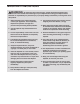
IMPORTANT PRECAUTIONS WARNING: To reduce the risk of serious injury, read all important precautions and instructions in this manual and all warnings on your elliptical before using your elliptical. Sears assumes no responsibility for personal injury or property damage sustained by or through the use of this product. 1. Before beginning any exercise program, consult your physician. This is especially important for persons over age 35 or persons with pre-existing health problems. 9.
BEFORE YOU BEGIN Thank you for purchasing the PROFORM® 390 E elliptical. The 390 E elliptical provides an array of features designed to make your workouts at home more effective and enjoyable. manual. To help us assist you, note the product model number and serial number before contacting us. The model number and the location of the serial number decal are shown on the front cover of this manual. For your benefit, read this manual carefully before you use the elliptical.
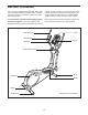
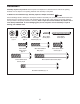
ASSEMBLY Assembly requires two persons. Place all parts of the elliptical in a cleared area and remove the packing materials. Do not dispose of the packing materials until assembly is completed. In addition to the included tool(s), assembly requires a Phillips screwdriver . See the drawings below to identify the small parts needed for assembly. The number in parentheses below each drawing is the key number of the part, from the PART LIST near the end of this manual.
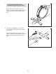
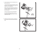
1. 1 To make assembly easier, read the information on page 5 before you begin. While a second person lifts the rear of the Frame (1), attach the Rear Stabilizer (70) to the Frame with two M10 x 85mm Patch Screws (82). 70 1 82 2. Orient the Front Stabilizer (73) so that the “Front” sticker is facing away from the front of the Frame (1). 2 73 While a second person lifts the front of the Frame (1), attach the Front Stabilizer (73) to the Frame with two M10 x 85mm Patch Screws (82).
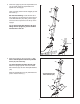
3. Orient the Upright (2) and the Top Shield Cover (37) as shown. Slide the Top Shield Cover upward onto the Upright. 3 Have a second person hold the Upright (2) near the Frame (1). Wire Tie See the inset drawing. Locate the wire tie in the Upright (2). Tie the lower end of the wire tie to the Wire Harness (42). Next, pull the upper end of the wire tie upward out of the top of the Upright. Tip: To prevent the Wire Harness (42) from falling into the Upright (2), secure the Wire Harness with a wire tie.
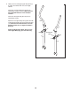
5. See the upper drawing. To avoid pinching or damaging the Pulse Wires (28) while you assemble the Handlebar (39), perform the following actions: 5 Insert the end of the left Pulse Wire (28) inside the left side of the Handlebar (39). 39 Then, insert the end of the right Pulse Wire (28) inside the right side of the Handlebar (39). See the lower drawing. Have a second person hold the Handlebar (39) in place around the Upright (2). 28 Tip: Avoid pinching the wires.
7. Untie and discard the wire tie attached to the Wire Harness (42). 7 Locate the Pulse Wires (28) inside the left and right sides of the Handlebar (39) and pull them upward out of the Upright (2). 4 42 While a second person holds the Console (4) near the Upright (2), connect the wires on the Console to the Wire Harness (42) and to the Pulse Wires (28). 28 Insert the excess wires into the Upright (2). Tip: Avoid pinching the wires.
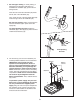
9. Identify the Left and Right Upper Body Arms (8, 9), which are marked with “Left” and “Right” stickers. 9 Orient the Left Upper Body Arm (8) and an Upper Body Leg (6) as shown. Make sure that the hexagonal holes are in the indicated location. Insert the Left Upper Body Arm (8) into the Upper Body Leg (6). 8 Attach the Left Upper Body Arm (8) with two M8 x 45mm Button Bolts (76) and two M8 Jam Nuts (77). Make sure that the Jam Nuts are in the hexagonal holes. Do not tighten the Button Bolts yet.
10. Apply a generous amount of the included grease to the axles on the Upright (2). Orient the Left and Right Upper Body Arms (8, 9) as shown, and slide them onto the left and right sides of the Upright (2). 10 8 Attach each Upper Body Arm (8, 9) with an M8 x 20mm Patch Screw (80) and an M8 Washer (33). 80 33 2 9 Grease 11. Apply a small amount of grease to a Shoulder Patch Bolt (31).
. See the inset drawing. Identify a Pivot Cover A (19), which has hooks, and a Pivot Cover B (22), which has tabs. 12 Press a Pivot Cover A (19) and a Pivot Cover B (22) together around the Right Upper Body Arm (9). Repeat this step for the other side of the elliptical. 8 Tabs Tip: Make sure that the Pivot Covers (19, 22) are positioned as shown. 22 Hooks 22 Hooks Orient the Front Upright Cover (16) so that the indicated arrow is pointing upward. 22 19 19 13.
15. Identify the Right Pedal (13), which is marked with a “Right” sticker. Attach the Right Pedal (13) to the Right Pedal Arm (49) with three M10 x 48mm Patch Screws (75) and three M10 Split Washers (78). Make sure to use the center hole and the two outer holes to attach the Right Pedal. 15 13 Attach the Left Pedal (not shown) to the Left Pedal Arm (not shown) in the same way. 78 16. Press the Rear Shield Cover (59) onto the Left and Right Shields (44, 45). 16 59 49 75 44 45 17.
HOW TO USE THE ELLIPTICAL HOW TO MOVE THE ELLIPTICAL HOW TO EXERCISE ON THE ELLIPTICAL Due to the size and weight of the elliptical, moving it requires two persons. Stand in front of the elliptical, hold the upright, and place one foot against one of the front wheels. Pull on the upright and have a second person lift the handle until the elliptical will roll on the wheels. Carefully move the elliptical to the desired location, and then lower it to the floor.
CONSOLE DIAGRAM FEATURES OF THE CONSOLE You can even connect your MP3 player or CD player to the console sound system and listen to your favorite music or audio books while you exercise. The advanced console offers an array of features designed to make your workouts more effective and enjoyable. To use the manual mode, see page 16. To use a preset workout, see page 17. To use the sound system, see page 17.
HOW TO USE THE MANUAL MODE The lower left display—This display will show the distance (total number of revolutions) that you have pedaled. 1. Turn on the console. The lower right display—This display will show your pedaling speed in revolutions per minute (rpm) and the approximate number of calories you have burned. Press any button or begin pedaling to turn on the console. When you turn on the console, the display will light. A tone will sound and the console will be ready for use.
7. When you are finished exercising, the console will turn off automatically. tance level is programmed for the next segment, the resistance level will flash in the display for a few seconds to alert you. The resistance of the pedals will then change. If the pedals do not move for several seconds, a series of tones will sound, the console will pause, and the time will flash in the display.
MAINTENANCE AND TROUBLESHOOTING Inspect and tighten all parts of the elliptical regularly. Replace any worn parts immediately. 44 To clean the elliptical, use a damp cloth and a small amount of mild soap. IMPORTANT: To avoid damage to the console, keep liquids away from the console and keep the console out of direct sunlight. 14 CONSOLE TROUBLESHOOTING If the console displays become dim, the batteries should be replaced; most console problems are the result of low batteries.
HOW TO ADJUST THE REED SWITCH Locate the Reed Switch (58). Loosen, but do not remove, the M4 x 16mm Screw (92). If the console does not display correct feedback, the reed switch should be adjusted. To adjust the reed switch, you must remove the right disc cover and the right pedal disc. Using a flat screwdriver, remove the right Disc Cover (18). 27 92 81 24 18 58 41 Next, rotate the Crank Assembly (24) until a Magnet (41) is aligned with the Reed Switch (58).
EXERCISE GUIDELINES WARNING: Burning Fat—To burn fat effectively, you must exercise at a low intensity level for a sustained period of time. During the first few minutes of exercise, your body uses carbohydrate calories for energy. Only after the first few minutes of exercise does your body begin to use stored fat calories for energy. If your goal is to burn fat, adjust the intensity of your exercise until your heart rate is near the lowest number in your training zone.
PART LIST Key No. Qty. 1 2 3 4 5 6 7 8 9 10 11 12 13 14 15 16 17 18 19 20 21 22 23 24 25 26 27 28 29 30 31 32 33 34 35 36 37 38 39 40 41 42 43 44 45 46 47 48 49 50 51 1 1 1 1 1 2 1 1 1 2 2 1 1 1 2 1 4 2 2 2 2 2 4 1 1 1 1 2 4 2 2 1 4 1 1 1 1 2 1 2 2 1 2 1 1 1 2 2 1 2 1 Description Key No. Qty.
85 30 33 29 22 80 8 29 17 33 15 84 12 75 78 19 17 11 78 84 78 10 6 14 23 21 31 76 95 77 23 92 20 5 79 79 3 78 78 78 79 79 2 4 92 29 92 29 85 10 28 79 33 30 78 15 84 39 93 75 78 79 79 13 78 19 32 49 84 77 17 21 6 89 23 17 33 23 9 16 31 20 76 80 22 11 EXPLODED DRAWING A Model No. 831.23943.
92 23 92 18 18 81 92 81 92 92 96 26 99 99 92 47 48 24 44 70 82 97 92 41 86 83 56 7 90 38 47 92 48 59 58 34 35 36 91 77 71 55 98 71 66 52 40 88 43 92 72 98 38 57 41 87 46 53 25 64 1 60 92 67 68 92 61 43 62 37 42 69 77 65 40 74 54 94 51 27 63 92 45 73 50 63 81 81 92 50 82 EXPLODED DRAWING B Model No. 831.23943.
Get it fixed, at your home or ours! Your Home For repair—in your home—of all major brand appliances, lawn and garden equipment, or heating and cooling systems, no matter who made it, no matter who sold it! For the replacement parts, accessories, and user’s manuals that you need to do-it-yourself. For Sears professional installation of home appliances and items like garage door openers and water heaters. 1-800-4-MY-HOME® (1-800-469-4663) Call anytime, day or night (U.S.A. and Canada) www.sears.com www.