www.proform.com Model No. PFEL04210.0 Serial No. Write the serial number in the space above for reference. Serial Number Decal QUESTIONS? If you have questions, or if parts are damaged or missing, DO NOT CONTACT THE STORE; please contact Customer Care. IMPORTANT: Please register this product (see the limited warranty on the back cover of this manual) before contacting Customer Care. 1-888-533-1333 CALL TOLL-FREE: Mon.–Fri. 6 a.m.–6 p.m. MT Sat. 8 a.m.–4 p.m. MT ON THE WEB: www.proformservice.
TABLE OF CONTENTS WARNING DECAL PLACEMENT . . . . . . . . . . . . . . . . . . . . . . . . . . . . . . . . . . . . . . . . . . . . . . . . . . . . . . . . . . . . . .2 IMPORTANT PRECAUTIONS . . . . . . . . . . . . . . . . . . . . . . . . . . . . . . . . . . . . . . . . . . . . . . . . . . . . . . . . . . . . . . . .3 BEFORE YOU BEGIN . . . . . . . . . . . . . . . . . . . . . . . . . . . . . . . . . . . . . . . . . . . . . . . . . . . . . . . . . . . . . . . . . . . . . .4 ASSEMBLY . . . . . . . . . . . . .
IMPORTANT PRECAUTIONS WARNING: To reduce the risk of serious injury, read all important precautions and instructions in this manual and all warnings on your elliptical before using your elliptical. ICON assumes no responsibility for personal injury or property damage sustained by or through the use of this product. 1. Before beginning any exercise program, consult your physician. This is especially important for persons over age 35 or persons with pre-existing health problems. 8.
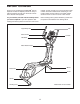
BEFORE YOU BEGIN Thank you for purchasing the PROFORM® 400 LE elliptical. The 400 LE elliptical provides an array of features designed to make your workouts at home more effective and enjoyable. manual. To help us assist you, note the product model number and serial number before contacting us. The model number and the location of the serial number decal are shown on the front cover of this manual. For your benefit, read this manual carefully before you use the elliptical.
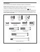
ASSEMBLY To hire an authorized service technician to assemble the elliptical, call 1-800-445-2480. Assembly requires two persons. Place all parts of the elliptical in a cleared area and remove the packing materials. Do not dispose of the packing materials until assembly is completed. In addition to the included tool(s), assembly requires a Phillips screwdriver . As you assemble the elliptical, use the drawings below to identify small parts.
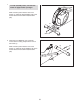
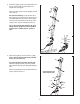
1. 1 To make assembly easier, read the information on page 5 before you begin. While a second person lifts the rear of the Frame (1), attach the Rear Stabilizer (70) to the Frame with two M10 x 85mm Patch Screws (82). 70 1 82 2. Orient the Front Stabilizer (73) so that the “Front” sticker is facing away from the front of the Frame (1). 2 73 While a second person lifts the front of the Frame (1), attach the Front Stabilizer (73) to the Frame with two M10 x 85mm Patch Screws (82).
3. Orient the Upright (2) and the Top Shield Cover (37) as shown. Slide the Top Shield Cover upward onto the Upright. 3 Wire Tie Have a second person hold the Upright (2) near the Frame (1). See the inset drawing. Locate the wire tie in the Upright (2). Tie the lower end of the wire tie to the Wire Harness (42). Next, pull the upper end of the wire tie upward out of the top of the Upright. Then, untie and discard the wire tie.
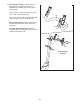
5. See the upper drawing. To avoid pinching or damaging the Pulse Wires (28) while you assemble the Handlebar (39), perform the following actions: 5 Insert the end of the left Pulse Wire (28) inside the left side of the Handlebar (39). 39 Then, insert the end of the right Pulse Wire (28) inside the right side of the Handlebar (39). See the lower drawing. Have a second person hold the Handlebar (39) in place around the Upright (2). 28 Tip: Avoid pinching the wires.
6. The Console (4) can use four D batteries (not included); alkaline batteries are recommended. IMPORTANT: If the Console has been exposed to cold temperatures, allow it to warm to room temperature before inserting batteries. Otherwise, you may damage the console displays or other electronic components. Remove the screws, remove the battery covers, insert the batteries into the battery compartments, and reattach the battery covers.
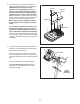
8. Attach the Console Cover (32) to the back of the Console (4) with two M4 x 48mm Screws (89). 8 4 32 89 9. Identify the Left and Right Upper Body Arms (8, 9), which are marked with “Left” and “Right” stickers. 9 Orient the Left Upper Body Arm (8) and an Upper Body Leg (6) as shown. Make sure that the hexagonal holes are in the indicated location. Insert the Left Upper Body Arm (8) into the Upper Body Leg (6).
10. Apply a generous amount of the included grease to the axles on the Upright (2). Orient the Left and Right Upper Body Arms (8, 9) as shown, and slide them onto the left and right sides of the Upright (2). 10 8 Attach each Upper Body Arm (8, 9) with an M8 x 20mm Patch Screw (80) and an M8 Washer (33). 80 33 2 9 Grease 11. Apply a small amount of grease to a Shoulder Patch Bolt (31).
. See the inset drawing. Identify a Pivot Cover A (19), which has hooks, and a Pivot Cover B (22), which has tabs. 12 Press a Pivot Cover A (19) and a Pivot Cover B (22) together around the Right Upper Body Arm (9). Repeat this step for the other side of the elliptical. Tip: Make sure that the Pivot Covers (19, 22) are positioned as shown. 8 Tabs 22 19 9 22 22 19 Hooks 19 Hooks 13. Attach the Rear Upright Cover (3) to the Upright (2) with three M4 x 16mm Screws (92).
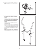
14. Press a Front Leg Cover (20) and a Rear Leg Cover (21) together around the right Upper Body Leg (6). 14 Repeat this step for the other side of the elliptical. 6 20 21 15. Identify the Right Pedal (13), which is marked with a “Right” sticker. Attach the Right Pedal (13) to the Right Pedal Arm (49) with three M10 x 48mm Patch Screws (75) and three M10 Split Washers (78). Make sure to use the center hole and the two outer holes to attach the Right Pedal.
16. Press the Rear Shield Cover (59) onto the Left and Right Shields (44, 45). 16 44 45 59 17. Make sure that all parts of the elliptical are properly tightened. Note: Some hardware may be left over after assembly is completed. To protect the floor or carpet from damage, place a mat under the elliptical.
HOW TO USE THE ELLIPTICAL HOW TO MOVE THE ELLIPTICAL HOW TO EXERCISE ON THE ELLIPTICAL Due to the size and weight of the elliptical, moving it requires two persons. Stand in front of the elliptical, hold the upright, and place one foot against one of the front wheels. Pull on the upright and have a second person lift the handle until the elliptical will roll on the wheels. Carefully move the elliptical to the desired location, and then lower it to the floor.
CONSOLE DIAGRAM FEATURES OF THE CONSOLE For example, lose unwanted pounds with the 8-week Weight Loss workout. iFit workouts control the resistance of the pedals while the voice of a personal trainer coaches you through your workouts. iFit cards are available separately. To purchase iFit cards, go to www.iFit.com or call the telephone number on the front cover of this manual. iFit cards are also available at select stores.
4. Follow your progress with the display. HOW TO USE THE MANUAL MODE The left display–This display can show the elapsed time and the approximate number of calories you have burned. The display will change modes every few seconds. 1. Turn on the console. Press any button or begin pedaling to turn on the console. When you turn on the console, the display will turn on. A tone will sound and the console will be ready for use. Note: During a workout, the display will show the time remaining in the workout.
5. Measure your heart rate if desired. 6. Turn on the fan if desired. If there are sheets of plastic on the Contacts metal contacts on the handgrip pulse sensor, remove the plastic. In addition, make sure that your hands are clean. To measure your heart rate, hold the handgrip pulse sensor with your palms resting against the metal contacts. Avoid moving your hands or gripping the contacts tightly. The fan has high and low speed settings.
HOW TO USE A PRESET WORKOUT At the end of each segment of the workout, a series of tones will sound and the next segment of the profile will begin to flash. If a different resistance level is programmed for the next segment, the resistance level will flash in the display for a few seconds to alert you. The resistance of the pedals will then change. 1. Turn on the console. See step 1 on page 17. 2. Select a preset workout.
HOW TO USE AN IFIT WORKOUT The duration of the workout will appear in the left display, the maximum resistance level for the workout will flash in the center display, and the number of the workout will appear in the right display. iFit cards are available separately. To purchase iFit cards, go to www.iFit.com or see the front cover of this manual. iFit cards are also available at select stores. 1. Turn on the console.
MAINTENANCE AND TROUBLESHOOTING Inspect and tighten all parts of the elliptical regularly. Replace any worn parts immediately. 44 To clean the elliptical, use a damp cloth and a small amount of mild soap. IMPORTANT: To avoid damage to the console, keep liquids away from the console and keep the console out of direct sunlight. 14 CONSOLE TROUBLESHOOTING 92 If the console displays become dim, replace all the batteries at the same time; most console problems are the result of low batteries.
HOW TO ADJUST THE REED SWITCH Locate the Reed Switch (58). Loosen, but do not remove, the M4 x 16mm Screw (92). If the console does not display correct feedback, the reed switch should be adjusted. To adjust the reed switch, you must remove the right disc cover and the right pedal disc. Using a flat screwdriver, remove the right Disc Cover (18). 27 92 81 58 18 41 24 Next, rotate the Crank Assembly (24) until a Magnet (41) is aligned with the Reed Switch (58).
EXERCISE GUIDELINES WARNING: Burning Fat—To burn fat effectively, you must exercise at a low intensity level for a sustained period of time. During the first few minutes of exercise, your body uses carbohydrate calories for energy. Only after the first few minutes of exercise does your body begin to use stored fat calories for energy. If your goal is to burn fat, adjust the intensity of your exercise until your heart rate is near the lowest number in your training zone.
SUGGESTED STRETCHES The correct form for several basic stretches is shown at the right. Move slowly as you stretch—never bounce. 1 1. Toe Touch Stretch Stand with your knees bent slightly and slowly bend forward from your hips. Allow your back and shoulders to relax as you reach down toward your toes as far as possible. Hold for 15 counts, then relax. Repeat 3 times. Stretches: Hamstrings, back of knees, and back. 2 2. Hamstring Stretch Sit with one leg extended.
PART LIST—Model No. PFEL04210.0 Key No. Qty. 1 2 3 4 5 6 7 8 9 10 11 12 13 14 15 16 17 18 19 20 21 22 23 24 25 26 27 28 29 30 31 32 33 34 35 36 37 38 39 40 41 42 43 44 45 46 47 48 49 50 1 1 1 1 1 2 1 1 1 2 2 1 1 1 2 1 4 2 2 2 2 2 4 1 1 1 1 2 4 2 2 1 4 1 1 1 1 2 1 1 2 1 7 1 1 1 2 2 1 2 Description Key No. Qty.
30 85 33 29 22 8 12 29 15 17 80 33 78 84 17 19 11 75 21 78 84 14 23 31 76 10 6 95 23 92 77 5 79 79 20 3 78 78 78 29 79 79 2 4 92 92 29 33 85 10 28 79 78 49 30 84 15 39 93 75 13 79 79 78 21 19 32 6 23 84 77 17 89 16 20 80 22 76 31 33 17 23 9 11 EXPLODED DRAWING A—Model No. PFEL04210.
26 18 41 92 46 92 41 92 92 27 47 48 18 92 70 82 24 91 44 43 91 38 96 96 96 91 43 91 86 92 88 47 58 92 92 43 72 48 59 57 38 40 71 66 35 90 52 53 77 1 60 92 68 67 92 61 43 62 37 25 64 42 69 94 65 74 36 54 7 56 34 77 71 55 91 83 87 51 27 63 92 45 73 50 50 82 81 92 63 EXPLODED DRAWING B—Model No. PFEL04210.
ORDERING REPLACEMENT PARTS To order replacement parts, please see the front cover of this manual.