www.proform.com Model No. PFEL64910.0 Serial No. Write the serial number in the space above for reference. Serial Number Decal (under frame) QUESTIONS? If you have questions, or if parts are damaged or missing, DO NOT CONTACT THE STORE; please contact Customer Care. IMPORTANT: Please register this product (see the limited warranty on the back cover of this manual) before contacting Customer Care. 1-888-533-1333 CALL TOLL-FREE: Mon.–Fri., 6 a.m.–6 p.m. MT Sat. 8 a.m.–4 p.m. MT ON THE WEB: www.
TABLE OF CONTENTS WARNING DECAL PLACEMENT . . . . . . . . . . . . . . . . . . . . . . . . . . . . . . . . . . . . . . . . . . . . . . . . . . . . . . . . . . . . . .2 IMPORTANT PRECAUTIONS . . . . . . . . . . . . . . . . . . . . . . . . . . . . . . . . . . . . . . . . . . . . . . . . . . . . . . . . . . . . . . . .3 BEFORE YOU BEGIN . . . . . . . . . . . . . . . . . . . . . . . . . . . . . . . . . . . . . . . . . . . . . . . . . . . . . . . . . . . . . . . . . . . . . .4 ASSEMBLY . . . . . . . . . . . . .
IMPORTANT PRECAUTIONS WARNING: To reduce the risk of serious injury, read all important precautions and instructions in this manual and all warnings on your elliptical before using your elliptical. ICON assumes no responsibility for personal injury or property damage sustained by or through the use of this product. 8. The elliptical should not be used by persons weighing more than 300 lbs. (136 kg). 1. Before beginning any exercise program, consult your physician.
BEFORE YOU BEGIN reading this manual, please see the front cover of this manual. To help us assist you, note the product model number and serial number before contacting us. The model number and the location of the serial number decal are shown on the front cover of this manual. Thank you for selecting the revolutionary PROFORM® 405 CE REAR DRIVE elliptical. The 405 CE REAR DRIVE elliptical provides an impressive selection of features designed to make your workouts at home more effective and enjoyable.
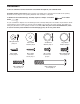
ASSEMBLY To hire an authorized service technician to assemble the elliptical, call 1-800-445-2480. Assembly requires two persons. Place all parts of the elliptical in a cleared area and remove the packing materials. Do not dispose of the packing materials until assembly is completed. In addition to the included tool(s), assembly requires a Phillips screwdriver mallet . and a rubber As you assemble the elliptical, use the drawings below to identify small parts.
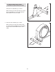
1. 1 To make assembly easier, read the information on page 5 before you begin. 3 100 Orient the Front Stabilizer (3) as shown. While another person lifts the Frame (1), attach the Front Stabilizer (3) to the Frame with two M10 x 80mm Patch Screws (100). 1 2. Orient the Rear Stabilizer (4) as shown. 2 While another person lifts the Folding Frame (2), attach the Rear Stabilizer (4) to the Folding Frame with two M10 x 80mm Patch Screws (100).
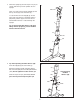
3. Orient the Upright (5) and the Top Cover (23) as shown. Slide the Top Cover upward onto the Upright. 3 Wire Tie Have a second person hold the Upright (5) and the Top Cover (23) near the Frame (1). Locate the wire tie in the Upright (5). Tie the lower end of the wire tie to the Wire Harness (60). Next, pull the upper end of the wire tie until the Wire Harness is routed through the Upright.
5. Apply a generous amount of the included grease to the Upright Axle (48) and to two Small Wave Washers (118). 5 102 Insert the Upright Axle (48) into the Upright (5) and center it. Slide a Small Wave Washer (118) onto each end of the Upright Axle. Identify the Right and Left Upper Body Legs (6, 7), which are marked with “Right” and “Left” stickers, and orient them as shown. 45 7 5 118 Grease 118 Grease Slide the Right and Left Upper Body Legs (6, 7) onto the Upright Axle (48).
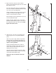
7. See drawing 7a. Apply grease to the axle on the right Crank Arm (39). 7a Orient a Pedal Arm Sleeve (46) so that the flat side is facing the elliptical. Slide the Pedal Arm Sleeve onto the axle on the right Crank Arm (39). Attach the Pedal Arm Sleeve (46) with an M8 x 25mm Patch Screw (113), a Crank Cap (43), and an M8 x 25mm Washer (45). Tip: Avoid damaging the Crank Cap when tightening the Patch Screw. Grease See drawing 7b.
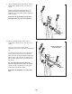
9. Identify the Right Upper Body Arm (8), which is marked with a “Right” sticker, and orient it as shown. 9 Attach the Right Upper Body Arm (8) to the Right Upper Body Leg (6) with three M8 x 16mm Patch Screws (102) and three M8 Split Washers (103). Attach the Left Upper Body Arm (9) to the Left Upper Body Leg (7) in the same way. 9 7 6 8 103 102 103 10. Identify the Right Handlebar (10), which is marked with a “Right” sticker, and orient it as shown.
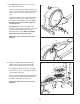
. The Console (33) can use four D batteries (not included); alkaline batteries are recommended. IMPORTANT: If the Console has been exposed to cold temperatures, allow it to warm to room temperature before inserting batteries. Otherwise, you may damage the console displays or other electronic components. Remove the screw, remove the battery cover, insert the batteries into the battery compartments, and reattach the battery cover.
13. Untie and discard the wire tie. 13 While a second person holds the Console (33) near the Upright (5), connect the console wires to the Wire Harness (60) and to the Pulse Wires (34). Avoid pinching the wires 33 Console Wires Insert the excess wire into the Console (33) or into the Upright (5). 34 Tip: Avoid pinching the wires. Attach the Console (33) to the Upright (5) with four M4 x 16mm Screws (93). 5 60 93 14.
15. Identify the Right Rear and Front Leg Covers (29, 30), which are marked with “Right” stickers. Attach the Right Rear Leg Cover (29) to the Right Upper Body Leg (6) with three M4 x 16mm Screws (93). 15 Attach the Right Front Leg Cover (30) around the Right Upper Body Leg (6) by pressing the tabs on the Right Front Leg Cover into the Right Rear Leg Cover (29). 31 Attach the Left Rear and Front Leg Covers (31, 32) in the same way. See step 4. Tighten the four M8 x 16mm Patch Screws (102).
HOW TO USE THE ELLIPTICAL HOW TO FOLD AND UNFOLD THE ELLIPTICAL To use the elliptical, first hold the handle, press the latch button, and lower the frame. When the elliptical is not in use, the frame can be folded out of the way. First, lift the latch under each pedal arm, and lift the pedal arms off the adjustment sleeves on the crank arms. Next, pull the pedal arms off the magnets on the upper body legs.
HOW TO EXERCISE ON THE ELLIPTICAL To mount the elliptical, hold the upper body arms or the handlebars and step onto the pedal that is in the lowest position. Next, step onto the other pedal. Push the pedals until they begin to move with a continuous motion. Note: The crank arms can turn in either direction. It is recommended that you turn the crank arms in the direction shown by the arrow; however, for variety, you can turn the crank arms in the opposite direction.
CONSOLE DIAGRAM FEATURES OF THE CONSOLE For example, lose unwanted pounds with the 8-week Weight Loss workout. iFit workouts control the resistance of the pedals while the voice of a personal trainer coaches you through your workouts. iFit cards are available separately. To purchase iFit cards, go to www.iFit.com or call the telephone number on the front cover of this manual. iFit cards are also available at select stores.
HOW TO USE THE MANUAL MODE The lower right display—The lower right display can show your pedaling speed and the approximate number of calories that you have burned. Note: Depending on the model of your elliptical, the display will show your pedaling speed in revolutions per minute or in miles or kilometers per hour. 1. Begin pedaling or press any button on the console to turn on the console. A moment after you begin pedaling or press a button, a tone will sound, and the display will turn on. 2.
5. Measure your heart rate if desired. HOW TO USE A PRESET WORKOUT If there are sheets of plastic Contacts on the metal contacts on the handgrip pulse sensor, remove the plastic. To measure your heart rate, hold the handgrip pulse sensor with your palms resting against the metal contacts. Avoid moving your hands or gripping the contacts tightly. 1. Begin pedaling or press any button on the console to turn on the console.
HOW TO USE AN IFIT WORKOUT The flashing segment of the profile represents the current segment of the workout. The height of the flashing segment indicates the resistance level for the current segment. At the end of each segment of the workout, a series of tones will sound and the next segment of the profile will begin to flash. If a different resistance level is programmed for the next segment, the resistance level will appear in the display for a few seconds to alert you.
HOW TO USE THE SOUND SYSTEM The upper display will show the currently selected backlight option. Press the Silent Magnetic Resistance increase button repeatedly to select the desired backlight option. To play music or audio books through the console sound system while you exercise, plug an audio cable (not included) into the jack on the console and into a jack on your MP3 player or CD player; make sure that the audio cable is fully plugged in. 3. Select a unit of measurement if desired.
MAINTENANCE AND TROUBLESHOOTING Inspect and tighten all parts of the elliptical regularly. Replace any worn parts immediately. Next, locate the Reed Switch (69). Loosen, but do not remove, the M4 x 16mm Screw (93). To clean the elliptical, use a damp cloth and a small amount of mild soap. IMPORTANT: To avoid damage to the console, keep liquids away from the console and keep the console out of direct sunlight.
HOW TO ADJUST THE DRIVE BELT Next, remove the M4 x 16mm Screws (93) and the M4 x 42mm Screws (106) from the Right and Left Shields (18, 19). Make sure to note which size of Screw you remove from each hole. Then, gently remove the Left Shield. If you can feel the pedals slip while you are pedaling, even when the resistance is adjusted to the highest level, the drive belt may need to be adjusted. To adjust the drive belt, you must remove the top shield and the left shield (see the instructions below).
EXERCISE GUIDELINES WARNING: Burning Fat—To burn fat effectively, you must exercise at a low intensity level for a sustained period of time. During the first few minutes of exercise, your body uses carbohydrate calories for energy. Only after the first few minutes of exercise does your body begin to use stored fat calories for energy. If your goal is to burn fat, adjust the intensity of your exercise until your heart rate is near the lowest number in your training zone.
PART LIST—Model No. PFEL64910.0 Key No. Qty. 1 2 3 4 5 6 7 8 9 10 11 12 13 14 15 16 17 18 19 20 21 22 23 24 25 26 27 28 29 30 31 32 33 34 35 36 37 38 39 40 41 42 43 44 45 46 47 48 49 50 1 1 1 1 1 1 1 1 1 1 1 1 1 1 1 2 2 1 1 1 1 1 1 1 1 1 2 2 1 1 1 1 1 2 2 2 4 1 1 1 1 1 2 2 6 2 4 1 2 2 Description Key No. Qty.
Key No. Qty. 101 102 103 104 105 106 107 108 109 110 1 18 14 2 2 4 2 2 2 2 Description Key No. Qty. Anchored Zip Tie M8 x 16mm Patch Screw M8 Split Washer M10 x 60mm Button Screw M10 Locknut M4 x 42mm Screw M10 x 25mm Button Screw M10 x 32mm Washer M8 x 16mm Button Screw M8 x 23.
50 102 102 93 103 103 26 44 49 52 51 17 15 13 114 9 35 93 49 44 50 111 102 28 53 55 54 12 58 58 45 31 17 51 52 93 116 45 56 102 54 27 26 7 93 117 24 48 118 111 14 58 45 5 93 103 93 57 103 102 112 11 102 32 34 102 58 56 57 93 27 118 93 33 29 6 54 59 55 103 45 93 116 103 30 28 102 54 102 53 103 10 93 34 25 35 102 103 8 EXPLODED DRAWING A—Model No. PFEL64910.
38 20 75 72 73 43 113 100 37 47 45 16 74 47 86 87 46 4 76 95 93 97 96 101 99 94 98 40 75 86 86 86 106 93 70 37 93 82 79 80 69 85 90 91 61 117 83 78 60 62 67 89 42 87 84 94 110 93 71 108 106 107 109 23 2 88 68 76 77 92 81 106 93 66 41 65 110 64 109 63 1 22 106 18 64 93 19 43 16 115 102 102 103 3 47 45 86 46 86 39 107 47 108 93 37 104 105 113 102 103 21 93 37 104 100 93 36 103 102 36 EXPLODED DRAWING B—
ORDERING REPLACEMENT PARTS To order replacement parts, see the front cover of this manual.