www.proform.com Model No. PFEL64911.0 Serial No. Write the serial number in the space above for reference. Serial Number Decal (under frame) QUESTIONS? If you have questions, or if parts are damaged or missing, DO NOT CONTACT THE STORE; please contact Customer Care. IMPORTANT: Please register this product (see the limited warranty on the back cover of this manual) before contacting Customer Care. CALL TOLL-FREE: 1-888-533-1333 Mon.–Fri., 6 a.m.–6 p.m. MT Sat. 8 a.m.–4 p.m. MT ON THE WEB: www.
TABLE OF CONTENTS WARNING DECAL PLACEMENT . . . . . . . . . . . . . . . . . . . . . . . . . . . . . . . . . . . . . . . . . . . . . . . . . . . . . . . . . . . . . . . 2 IMPORTANT PRECAUTIONS . . . . . . . . . . . . . . . . . . . . . . . . . . . . . . . . . . . . . . . . . . . . . . . . . . . . . . . . . . . . . . . . . . 3 BEFORE YOU BEGIN. . . . . . . . . . . . . . . . . . . . . . . . . . . . . . . . . . . . . . . . . . . . . . . . . . . . . . . . . . . . . . . . . . . . . . . .
IMPORTANT PRECAUTIONS WARNING: To reduce the risk of serious injury, read all important precautions and instructions in this manual and all warnings on your elliptical before using your elliptical. ICON assumes no responsibility for personal injury or property damage sustained by or through the use of this product. 1. Before beginning any exercise program, consult your physician. This is especially important for persons over age 35 or persons with pre-existing health problems. 9.
BEFORE YOU BEGIN Thank you for selecting the revolutionary PROFORM® 410 CE elliptical. The 410 CE elliptical provides an impressive selection of features designed to make your workouts at home more effective and enjoyable. manual. To help us assist you, note the product model number and serial number before contacting us. The model number and the location of the serial number decal are shown on the front cover of this manual. For your benefit, read this manual carefully before you use the elliptical.
PART IDENTIFICATION CHART Use the drawings below to identify the small parts needed for assembly. The number in parentheses below each drawing is the key number of the part, from the PART LIST near the end of this manual. The number following the key number is the quantity needed for assembly. Note: If a part is not in the hardware kit, check to see if it has been preassembled. Extra parts may be included.
ASSEMBLY • To hire an authorized service technician to assemble the elliptical, call 1-800-445-2480. • In addition to the included tool(s), assembly requires the following tools: • Assembly requires two persons. one Phillips screwdriver • Place all parts in a cleared area and remove the packing materials. Do not dispose of the packing materials until you complete all assembly steps. one rubber mallet Assembly may be easier if you have a socket set or a set of ratchet wrenches.
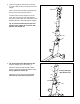
3. Orient the Upright (5) and the Top Cover (23) as shown. Slide the Top Cover upward onto the Upright. 3 Wire Tie Have a second person hold the Upright (5) and the Top Cover (23) near the Frame (1). Locate the wire tie in the Upright (5). Tie the lower end of the wire tie to the Wire Harness (60). Next, pull the upper end of the wire tie until the Wire Harness is routed through the Upright.
5. Using a small plastic bag to keep your fingers clean, apply a generous amount of the included grease to the Upright Axle (48) and to two Small Wave Washers (118). 5 102 45 7 Insert the Upright Axle (48) into the Upright (5) and center it. Slide a Small Wave Washer (118) onto each end of the Upright Axle. 5 6 118 Identify the Right and Left Upper Body Legs (6, 7), which are marked with “Right” and “Left” stickers, and orient them as shown.
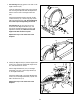
7. See drawing 7a. Apply grease to the axle on the Right Crank Arm (39). 7a Orient an Adjustment Sleeve (46) so that the flat side is facing the elliptical. Slide the Adjustment Sleeve onto the axle on the Right Crank Arm (39). Attach the Adjustment Sleeve (46) with an M8 x 25mm Screw (113), a Crank Cap (43), and an M8 x 25mm Washer (45). Tip: Avoid damaging the Crank Cap when tightening the Screw. Grease 39 See drawing 7b.
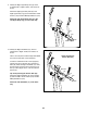
9. Identify the Right Upper Body Arm (8), which is marked with a “Right” sticker, and orient it as shown. 9 Attach the Right Upper Body Arm (8) to the Right Upper Body Leg (6) with three M8 x 16mm Screws (102) and three M8 Split Washers (103). Attach the Left Upper Body Arm (9) to the Left Upper Body Leg (7) in the same way. 9 7 6 8 103 102 103 10. Identify the Right Handlebar (10), which is marked with a “Right” sticker, and orient it as shown.
. The Console (33) can use four D batteries (not included); alkaline batteries are recommended. Do not use old and new batteries together or alkaline, standard, and rechargeable batteries together. IMPORTANT: If the Console has been exposed to cold temperatures, allow it to warm to room temperature before inserting batteries. Otherwise, you may damage the console displays or other electronic components. Remove the screw and the battery cover, and insert batteries into the battery compartment.
13. Untie and discard the wire tie on the Wire Harness (60). 13 33 While a second person holds the Console (33) near the Upright (5), connect the wires on the Console to the Wire Harness (60) and to the Sensor Wires (34). Avoid pinching the wires 34 Insert the excess wire into the Console (33) or into the Upright (5). Tip: Avoid pinching the wires. Attach the Console (33) to the Upright (5) with four M4 x 16mm Screws (93). 5 60 93 14.
15. Identify the Right Rear and Front Leg Covers (29, 30), which are marked with “Right” stickers. 15 Attach the Right Rear Leg Cover (29) to the Right Upper Body Leg (6) with three M4 x 16mm Screws (93). Attach the Right Front Leg Cover (30) around the Right Upper Body Leg (6) by pressing the tabs on the Right Front Leg Cover into the Right Rear Leg Cover (29). 30 32 31 6 Attach the Left Rear and Front Leg Covers (31, 32) in the same way. See step 4. Tighten the four M8 x 16mm Screws (102).
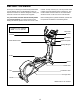
HOW TO USE THE ELLIPTICAL HOW TO FOLD AND UNFOLD THE ELLIPTICAL To unfold the elliptical for use, first hold the handle, press the latch button, and lower the frame. When the elliptical is not in use, the frame can be folded out of the way. Next, pull the pedal arms off the magnets on the upper body legs. Then, lift the latches under the pedal arms, and set the pedal arms on the adjustment sleeves on the crank arms.
HOW TO EXERCISE ON THE ELLIPTICAL HOW TO ELIMINATE FLEXING IN THE CENTER OF THE ELLIPTICAL To mount the elliptical, hold the upper body arms or the handlebars and step onto the pedal that is in the lowest position. Next, step onto the other pedal. Push the pedals until they begin to move with a continuous motion. Note: The crank arms can turn in either direction.
FEATURES OF THE CONSOLE CONSOLE DIAGRAM The console offers an array of features designed to make your workouts more effective and enjoyable. When you use the manual mode of the console, you can change the resistance of the pedals with the touch of a button. While you exercise, the console will display continuous exercise feedback. You can even measure your heart rate using the handgrip heart rate monitor. The console also offers eight timed workouts.
HOW TO USE THE MANUAL MODE The lower right display—The lower right display can show the your pedaling speed in revolutions per minute (rpm) and the approximate number of calories that you have burned. Note: When a weight loss workout is selected, the display will count down the number of calories to be burned. 1. Begin pedaling or press any button on the console to turn on the console. A moment after you begin pedaling or press a button, the display will turn on. 2. Select the manual mode.
5. Measure your heart rate if desired. If the display does not show your heart rate, make sure that your hands are positioned as described. Be careful not to move your hands excessively or to squeeze the contacts tightly. For optimal performance, clean the contacts using a soft cloth; never use alcohol, abrasives, or chemicals to clean the contacts. If there are sheets of plastic on the Contacts metal contacts on the handgrip heart rate monitor, remove the plastic.
HOW TO USE A TIMED WORKOUT At the end of each segment of the workout, a series of tones will sound and the next segment of the profile will begin to flash. If a different resistance level is programmed for the next segment, the resistance level will appear in the display for a few seconds to alert you. The resistance of the pedals will then change. 1. Begin pedaling or press any button on the console to turn on the console. A moment after you begin pedaling or press a button, the display will turn on. 2.
HOW TO USE A WEIGHT LOSS WORKOUT At the end of each segment of the workout, a series of tones will sound and the next segment of the profile will begin to flash. If a different resistance level is programmed for the next segment, the resistance level will appear in the display for a few seconds to alert you. The resistance of the pedals will then change. 1. Begin pedaling or press any button on the console to turn on the console.
HOW TO USE AN IFIT WORKOUT HOW TO USE THE SOUND SYSTEM iFit cards are available separately. To purchase iFit cards, go to www.iFit.com or see the front cover of this manual. iFit cards are also available at select stores. To play music or audio books through the console sound system while you exercise, plug the audio cable into the jack on the console and into a jack on your MP3 player or CD player; make sure that the audio cable is fully plugged in. 1.
FCC INFORMATION This equipment has been tested and found to comply with the limits for a Class B digital device, pursuant to part 15 of the FCC Rules. These limits are designed to provide reasonable protection against harmful interference in a residential installation. This equipment generates, uses, and can radiate radio frequency energy and, if not installed and used in accordance with the instructions, may cause harmful interference to radio communications.
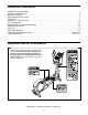
MAINTENANCE AND TROUBLESHOOTING Inspect and tighten all parts of the elliptical regularly. Replace any worn parts immediately. Next, locate the Reed Switch (69). Loosen, but do not remove, the M4 x 16mm Screw (93). To clean the elliptical, use a damp cloth and a small amount of mild soap. IMPORTANT: To avoid damage to the console, keep liquids away from the console and keep the console out of direct sunlight. 93 69 CONSOLE TROUBLESHOOTING 74 75 Most console problems are the result of low batteries.
HOW TO ADJUST THE DRIVE BELT If you can feel the pedals slip while you are pedaling, even when the resistance is adjusted to the highest level, the drive belt may need to be adjusted. Next, remove the M4 x 16mm Screws (93) and the M4 x 42mm Screws (106) from the Right and Left Shields (18, 19). Make sure to note which size of Screw you remove from each hole. Then, gently remove the Left Shield. To adjust the drive belt, you must remove the top shield and the left shield (see the instructions below).
EXERCISE GUIDELINES Burning Fat—To burn fat effectively, you must exercise at a low intensity level for a sustained period of time. During the first few minutes of exercise, your body uses carbohydrate calories for energy. Only after the first few minutes of exercise does your body begin to use stored fat calories for energy. If your goal is to burn fat, adjust the intensity of your exercise until your heart rate is near the lowest number in your training zone.
SUGGESTED STRETCHES The correct form for several basic stretches is shown at the right. Move slowly as you stretch—never bounce. 1. Toe Touch Stretch Stand with your knees bent slightly and slowly bend forward from your hips. Allow your back and shoulders to relax as you reach down toward your toes as far as possible. Hold for 15 counts, then relax. Repeat 3 times. Stretches: Hamstrings, back of knees and back. 1 2. Hamstring Stretch 2 Sit with one leg extended.
NOTES 27
PART LIST Key No. Qty. 1 2 3 4 5 6 7 8 9 10 11 12 13 14 15 16 17 18 19 20 21 22 23 24 25 26 27 28 29 30 31 32 33 34 35 36 37 38 39 40 41 42 43 44 45 46 47 48 49 50 1 1 1 1 1 1 1 1 1 1 1 1 1 1 1 2 2 1 1 1 1 1 1 1 1 1 2 2 1 1 1 1 1 2 2 2 4 1 1 1 1 1 2 2 8 2 4 1 2 2 Model No. PFEL64911.0 R0112A Description Key No. Qty.
Key No. Qty. 101 102 103 104 105 106 107 108 109 110 111 112 113 114 115 116 117 1 18 14 2 4 4 2 2 4 2 8 1 2 1 1 2 5 Description Key No. Qty. Anchored Zip Tie M8 x 16mm Screw M8 Split Washer M10 x 60mm Button Screw M10 Locknut M4 x 42mm Screw M10 x 25mm Button Screw M10 x 32mm Washer M8 x 16mm Button Screw M8 x 23.
50 102 102 30 93 13 44 49 52 51 128 126 17 127 103 103 9 129 125 93 49 44 114 111 45 116 51 52 93 130 109 45 129 111 7 93 27 112 54 58 58 53 55 17 109 28 45 31 45 12 102 15 122 102 56 105 50 124 130 129 111 35 48 24 103 102 11 129 128 124 123 126 125 127 45 58 5 57 93 103 93 111 118 102 105 14 117 26 54 32 34 58 102 118 27 56 57 93 93 33 29 6 54 59 55 103 45 93 116 30 28 103 102 54 102 53 103 10 93 34
38 20 75 72 73 43 113 100 37 47 45 16 74 47 86 87 46 76 4 75 40 95 93 97 96 61 70 37 93 69 85 81 82 91 80 79 90 120 101 99 94 98 86 86 86 106 93 78 117 60 62 93 67 107 42 94 87 84 110 71 108 106 93 89 109 121 23 2 88 68 76 83 77 92 119 106 66 41 65 110 64 109 1 22 106 18 64 93 19 107 102 102 103 3 43 16 115 47 45 86 46 47 108 86 39 63 93 37 104 105 113 102 103 21 93 37 104 100 93 36 103 102 36 EXPLODED
ORDERING REPLACEMENT PARTS To order replacement parts, please see the front cover of this manual.