www.proform.com Model No. PFEL04910.0 Serial No. Write the serial number in the space above for reference. Serial Number Decal QUESTIONS? If you have questions, or if parts are damaged or missing, DO NOT CONTACT THE STORE; please contact Customer Care. IMPORTANT: Please register this product (see the limited warranty on the back cover of this manual) before contacting Customer Care. 1-888-533-1333 CALL TOLL-FREE: Mon.–Fri. 6 a.m.–6 p.m. MT Sat. 8 a.m.–4 p.m. MT ON THE WEB: www.proformservice.
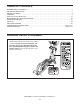
TABLE OF CONTENTS WARNING DECAL PLACEMENT . . . . . . . . . . . . . . . . . . . . . . . . . . . . . . . . . . . . . . . . . . . . . . . . . . . . . . . . . . . . . .2 IMPORTANT PRECAUTIONS . . . . . . . . . . . . . . . . . . . . . . . . . . . . . . . . . . . . . . . . . . . . . . . . . . . . . . . . . . . . . . . .3 BEFORE YOU BEGIN . . . . . . . . . . . . . . . . . . . . . . . . . . . . . . . . . . . . . . . . . . . . . . . . . . . . . . . . . . . . . . . . . . . . . .4 ASSEMBLY . . . . . . . . . . . . .
IMPORTANT PRECAUTIONS WARNING: To reduce the risk of serious injury, read all important precautions and instructions in this manual and all warnings on your elliptical before using your elliptical. ICON assumes no responsibility for personal injury or property damage sustained by or through the use of this product. 1. Before beginning any exercise program, consult your physician. This is especially important for persons over age 35 or persons with pre-existing health problems. 9.
BEFORE YOU BEGIN Thank you for purchasing the PROFORM® 500 LE elliptical. The 500 LE elliptical provides an array of features designed to make your workouts at home more effective and enjoyable. manual. To help us assist you, note the product model number and serial number before contacting us. The model number and the location of the serial number decal are shown on the front cover of this manual. For your benefit, read this manual carefully before you use the elliptical.
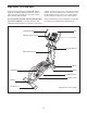
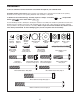
ASSEMBLY To hire an authorized service technician to assemble the elliptical, call 1-800-445-2480. Assembly requires two persons. Place all parts of the elliptical in a cleared area and remove the packing materials. Do not dispose of the packing materials until assembly is completed. In addition to the included tool(s), assembly requires a Phillips screwdriver wrench , and a rubber mallet . , an adjustable Use the drawings below to identify the small parts needed for assembly.
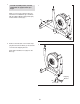
1. To make assembly easier, read the information on page 5 before you begin. 1 While a second person lifts the Base (1), attach the Front Stabilizer (6) to the Base with two M10 x 80mm Carriage Bolts (82) and two M10 Locknuts (81). 82 6 81 81 2. Remove the indicated screw and the shipping bracket from the Base (1). Discard the screw and the shipping bracket. 1 2 Next, tighten the Base Foot (26) into the Base (1).
3. Attach the Rear Stabilizer (7) to the Frame (2) with two M10 x 127mm Patch Screws (83). 3 83 Next, hold the handle on the Frame (2), press the Latch Button (68), and lower the Frame until the Rear Stabilizer (7) rests on the floor. 7 Handle 2 68 4. Hold a Hub Cover (75) and a Crank Arm (36) against the Crank (45). Align the holes in the Hub Cover (75) and the Crank Arm (36) with the unused holes in the left side of the Crank (45).
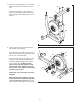
5. While a second person holds the Upright (3) near the Base (1), connect the Upper Wire Harness (48) to the Lower Wire Harness (49). 5 Tip: Avoid pinching the wires. Insert the Upright (3) into the Base (1). Avoid pinching the wires Attach the Upright (3) with an M8 x 69mm Button Bolt (80), an M8 Split Washer (90), and an M8 Jam Nut (79). Do not tighten the Button Bolt yet; make sure that the Jam Nut is in the hexagonal hole in the Base.
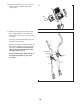
7. Identify the Left and Right Handlebars (119, 120), which are marked with “Left” and “Right” stickers, and orient them as shown. 7 Tip: Avoid pinching the Pulse Wires (118). Attach the Left and Right Handlebars (119, 120) to the Upright (3) with two M8 x 80mm Patch Bolts (116) and two M8 Jam Nuts (79). 116 3 119 79 120 116 118 118 Avoid pinching the wires 8. Insert the Pulse Wires (118) upward through the Upright (3) as shown. 8 3 118 118 9.
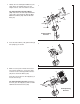
. Attach the Upright Cap (4) to the Console (5) with two M4 x 16mm Round Head Screws (101). 10 5 4 101 11. Identify the Left Upper Body Arm (8) and the Left Upper Body Leg (11), which are marked with “Left” stickers, and orient them as shown. 11 Insert the Left Upper Body Arm (8) into the Left Upper Body Leg (11). 9 8 Attach the Left Upper Body Arm (8) with two M8 x 41mm Button Bolts (78) and two M8 Jam Nuts (79).
12. Using a small plastic bag to keep your fingers clean, apply a generous amount of the included grease to the Pivot Axle (74). Insert the Pivot Axle into the Upright (3) and center it. Orient the Left Upper Body Leg (11) as shown, and slide it onto the left end of the Pivot Axle (74). Slide the Right Upper Body Leg (12) onto the right end of the Pivot Axle. Tighten an M8 x 23mm Patch Screw (84) with an M8 Washer (88) and a Wave Washer (111) into each end of the Pivot Axle (74) at the same time.
14. Identify the Left Pedal (13) and the Left Pedal Arm (14), which are marked with “Left” stickers. 14 13 Attach the Left Pedal (13) to the Left Pedal Arm (14) with an M4 x 50mm Screw (108), three M4 x 16mm Blunt Screws (104), four M4 Split Washers (112), and four M4 Washers (102). 102 Attach the Right Pedal (not shown) to the Right Pedal Arm (not shown) in the same way. 15. Apply a small amount of grease to one of the Pedal Arm Axles (32).
16. Lift the latch on the underside of the Left Pedal Arm (14), and set the Left Pedal Arm on the left Crank Bushing Sleeve (43). 16 Release the lever, and make sure that the Left Pedal Arm (14) is securely connected to the Crank Bushing Sleeve (43). Connect the Right Pedal Arm (not shown) in the same way. 14 See step 5. Tighten the M8 x 69mm Button Bolt (80) and the two M8 x 23mm Patch Screws (84). 17. See the upper drawing. Plug the Power Adapter (121) into the receptacle on the Console (5).
HOW TO USE THE ELLIPTICAL HOW TO PLUG IN THE POWER ADAPTER IMPORTANT: If the elliptical has been exposed to cold temperatures, allow it to warm to room temperature before plugging in the power adapter. If you do not do this, you may damage the console displays or other electronic components. Plug the power adapter into the receptacle on the console. Then, plug the power adapter into an appropriate outlet that is properly installed in accordance with all local codes and ordinances.
HOW TO EXERCISE ON THE ELLIPTICAL Note: The crank arms can turn in either direction. It is recommended that you turn the crank arms in the direction shown by the arrow; however, for variety, you can turn the crank arms in the opposite direction. To mount the elliptical, hold the upper body arms or the handlebars and step onto the pedal that is in the lowest position. Next, step onto the other pedal. Push the pedals until they begin to move with a continuous motion.
CONSOLE DIAGRAM FEATURES OF THE CONSOLE For example, lose unwanted pounds with the 8-week Weight Loss workout. iFit workouts control the resistance of the pedals while the voice of a personal trainer coaches you through your workouts. iFit cards are available separately. To purchase iFit cards, go to www.iFit.com or call the telephone number on the front cover of this manual. iFit cards are also available at select stores.
4. Follow your progress with the display. HOW TO USE THE MANUAL MODE The left display–This display can show the elapsed time and the approximate number of calories you have burned. The display will change modes every few seconds. 1. Turn on the console. Press any button or begin pedaling to turn on the console. When you turn on the console, the display will turn on. A tone will sound and the console will be ready for use. Note: During a workout, the display will show the time remaining in the workout.
5. Measure your heart rate if desired. 6. Turn on the fan if desired. If there are sheets of plastic Contacts on the metal contacts on the handgrip pulse sensor, remove the plastic. In addition, make sure that your hands are clean. To measure your heart rate, hold the handgrip pulse sensor with your palms resting against the metal contacts. Avoid moving your hands or gripping the contacts tightly. The fan has high and low speed settings.
HOW TO USE A PRESET WORKOUT At the end of each segment of the workout, a series of tones will sound and the next segment of the profile will begin to flash. If a different resistance level is programmed for the next segment, the resistance level will flash in the display for a few seconds to alert you. The resistance of the pedals will then change. 1. Turn on the console. See step 1 on page 17. 2. Select a preset workout.
HOW TO USE AN IFIT WORKOUT The duration of the workout will appear in the left display, the maximum resistance level for the workout will flash in the center display, and the number of the workout will appear in the right display. iFit cards are available separately. To purchase iFit cards, go to www.iFit.com or see the front cover of this manual. iFit cards are also available at select stores. 1. Turn on the console.
MAINTENANCE AND TROUBLESHOOTING HOW TO LEVEL THE ELLIPTICAL Inspect and tighten all parts of the elliptical regularly. Replace any worn parts immediately. If the elliptical rocks slightly on your floor during use, turn one or both of the leveling feet beneath the rear stabilizer until the rocking motion is eliminated. To clean the elliptical, use a damp cloth and a small amount of mild soap.
EXERCISE GUIDELINES WARNING: Burning Fat—To burn fat effectively, you must exercise at a low intensity level for a sustained period of time. During the first few minutes of exercise, your body uses carbohydrate calories for energy. Only after the first few minutes of exercise does your body begin to use stored fat calories for energy. If your goal is to burn fat, adjust the intensity of your exercise until your heart rate is near the lowest number in your training zone.
SUGGESTED STRETCHES The correct form for several basic stretches is shown at the right. Move slowly as you stretch—never bounce. 1. Toe Touch Stretch 1 Stand with your knees bent slightly and slowly bend forward from your hips. Allow your back and shoulders to relax as you reach down toward your toes as far as possible. Hold for 15 counts, then relax. Repeat 3 times. Stretches: Hamstrings, back of knees and back. 2. Hamstring Stretch 2 Sit with one leg extended.
PART LIST Key No. Qty. 1 2 3 4 5 6 7 8 9 10 11 12 13 14 15 16 17 18 19 20 21 22 23 24 25 26 27 28 29 30 31 32 33 34 35 36 37 38 39 40 41 42 43 44 45 46 47 48 49 50 1 1 1 1 1 1 1 1 1 2 1 1 1 1 1 1 1 1 1 1 1 1 2 2 2 1 2 1 1 6 4 2 4 1 2 2 2 1 1 1 2 4 2 2 1 1 2 1 1 1 Description Key No. Qty.
Key No. Qty. 101 102 103 104 105 106 107 108 109 110 111 112 10 12 26 8 6 2 4 2 2 2 2 8 Description Key No. Qty.
EXPLODED DRAWING A 105 111 88 84 79 79 17 30 78 115 31 80 79 90 88 115 33 112 90 90 19 32 33 48 3 84 102 13 30 101 73 88 30 101 101 30 11 116 31 39 116 112 108 102 104 31 115 84 112 104 14 26 30 84 111 78 12 21 10 118 73 15 32 88 31 9 115 16 102 33 88 88 30 60 33 88 1 101 104 22 79 74 49 84 105 20 101 119 18 105 120 101 117 8 117 5 4 101 10 Model No. PFEL04910.
EXPLODED DRAWING B 54 52 91 94 77 94 94 77 92 110 Model No. PFEL04910.
ORDERING REPLACEMENT PARTS To order replacement parts, please see the front cover of this manual.