
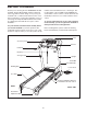
User`s manual

10
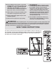
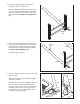
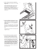
11. Lower the Uprights (38, 39).
See the inset drawing. Position the Uprights (38,
39) so that the treadmill Frame (36) is centered
between the Uprights.
Firmly tighten the Upright Bolts (4) on each side
of the treadmill.
39
38, 39
36
38
View from Above
Side View
11
4
2
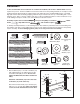
10. Set the Console Base (67) onto the top of the
Handrails (40). Next, start the two Console Bolts
(2) with 1/4” Star Washers (8) into the Handrails
and the Console Base.
Do not fully tighten the
Bolts yet. Start all four 3/4” Screws (3) before
t
ightening them.
B
e careful not to overtighten
t
he Screws. Tighten the two Console Bolts.
3
2
8
8
3
40
4
0
10
67
Front View
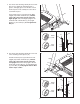
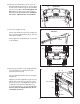
12.
Attach the ground wire on the Upright Wire (69)
to the indicated hole in the Base (37) with a
Silver Ground Screw (10).
Press the indicated Grommet (72) into the Right
Upright (39).
Align the holes in the Right Base Leg Cover (42)
with the holes in the Base (37). Note: It may be
necessary to press on the Right Base Leg Cover
to align the holes. Attach the Right Base Leg
Cover (42) with three 1/2" Screws (83).
Be care-
ful not to pinch the Upright Wire (69). Do not
overtighten the Screws.
42
37
69
39
83
72
Ground Wire
83
12
10
83