
User`s manual
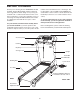

ASSEMBLY
To hire an authorized service technician to assemble the treadmill, call toll-free 1-800-445-2480. Assembly
requires two persons. Set the treadmill in a cleared area and remove the packing materials; do not dispose of the
packing materials until assembly is completed. Note: The underside of the treadmill walking belt is coated with
high-performance lubricant. During shipping, lubricant may be transferred to the top of the walking belt or to the
shipping carton. This is a normal condition and does not affect treadmill performance. If there is lubricant on top
of the walking belt, wipe it off with a soft cloth and mild, non-abrasive cleaner.
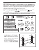
Assembly requires the included hex keys and your own phillips screwdriver , rubber
mallet , adjustable wrench , and needlenose pliers .
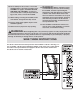
To identify assembly hardware, see the drawings below. The number in parentheses below each drawing is the
key number of the part, from the PART LIST on page 23. The number following the parentheses is the quantity
used in assembly.
To avoid damaging plastic parts, do not use power tools for assembly.
1/2” Screw (119)–1
1
3
/4” Tek Screw (58)–8
1
3/4" Screw (3)–6
Upright Washer
(7)–2
Silver Ground
Screw (10)–2
Wheel Spacer
(94)–4
Console
Bolt (2)–2
1/4” Star Washer
(8)–2
Wheel Nut (90)–2
Wheel Bolt (5)–2
Frame Bolt (1)–2
1/2" Screw
(83)–8
Screw (90)–2
F
Nut (12)–2
Upright Bolt (4)–4
Handrail Bolt (9)–4
Upright Star
Washer (6)–4
F
Handrail Star
Washer (11)–4
1 1/2" Screw (66)–4
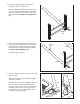
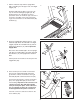
1. Attach a Wheel (74) to one side of the Base (37)
with a Wheel Bolt (5), two Wheel Spacers (94),
and a Wheel Nut (90) as shown. Do not over-
tighten the Wheel Nut; the Wheel should turn
freely.
Attach the other Wheel (74) to the other side
of the Base (37) in the same way.
Attach the four Base Pads (51) to the Base (37)
with four 1 1/2” Screws (66); make sure that the
screws are in the indicated holes in the Base.
1
37
74
74
94
94
5
Hole
Hole
Hole
51
66
66
66
66
51
51
Hole
51
90
6