Model No. PFTL49707.0 Serial No. USER'S MANUAL Write the serial number in the space above for future reference. Serial Number Decal QUESTIONS? As a manufacturer, we are committed to providing complete customer satisfaction. If you have questions, or if parts are missing, PLEASE DO NOT CONTACT THE STORE; please contact Customer Care. IMPORTANT: You must note the product model number and serial number (see the drawing above) before contacting us: CALL TOLL-FREE: 1-888-533-1333 Mon.–Fri. 6 a.m.–6 p.m.
TABLE OF CONTENTS WARNING DECAL PLACEMENT . . . . . . . . . . . . . . . . . . . . . . . . . . . . . . . . . . . . . . . . . . . . . . . . . . . . . . . . . . . . . .2 IMPORTANT PRECAUTIONS . . . . . . . . . . . . . . . . . . . . . . . . . . . . . . . . . . . . . . . . . . . . . . . . . . . . . . . . . . . . . . . .3 BEFORE YOU BEGIN . . . . . . . . . . . . . . . . . . . . . . . . . . . . . . . . . . . . . . . . . . . . . . . . . . . . . . . . . . . . . . . . . . . . . .5 ASSEMBLY . . . . . . . . . . . . . .
IMPORTANT PRECAUTIONS WARNING: To reduce the risk of serious injury, read all important precautions and instructions in this manual and all warnings on your treadmill before using your treadmill. ICON assumes no responsibility for personal injury or property damage sustained by or through the use of this product. 1. Before beginning any exercise program, consult your physician. This is especially important for persons over the age of 35 or persons with pre-existing health problems.
20. Never leave the treadmill unattended while it is running. Always remove the key, unplug the power cord, and switch the reset/off circuit breaker to the off position when the treadmill is not in use. (See the drawing on page 5 for the location of the circuit breaker.) 24. Inspect and properly tighten all parts of the treadmill regularly. 25. Never insert any object into any opening on the treadmill. 26.
BEFORE YOU BEGIN ual. To help us assist you, note the product model number and serial number before contacting us. The model number and the location of the serial number decal are shown on the front cover of this manual. Thank you for selecting the new PROFORM® 515 TR treadmill. The 515 TR treadmill combines advanced technology with innovative design to help you get the most from your exercise in the convenience of your home.
ASSEMBLY To hire an authorized service technician to assemble the treadmill, call toll-free 1-800-445-2480. Assembly requires two persons. Set the treadmill in a cleared area and remove the packing materials; do not dispose of the packing materials until assembly is completed. Note: The underside of the treadmill walking belt is coated with high-performance lubricant. During shipping, lubricant may be transferred to the top of the walking belt or to the shipping carton.
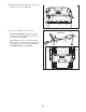
2. Orient the Left Upright (31) as shown, and attach it to the Base (48) with two 3/8" x 2 1/4" Bolts (40) and two 3/8" Star Washers (39); do not tighten the Bolts yet. 2 Latch Holes 48 31 39 39 3. Attach a Wheel (45) to each side of the Base (48) with a 3/8" x 2 1/4" Bolt (40), two Wheel Spacers (44), and a 3/8" Nut (47) as shown. Do not overtighten the Bolts; the Wheels should turn freely. 3 45 44 44 40 47 45 44 44 47 48 40 4.
5. See the left inset drawing. Identify the two Frame Spacers (34). Open the included packet of grease, and apply grease to both sides of both Frame Spacers. Then, identify the outer side of each Frame Spacer. 5 31 36 47 Hold a Frame Spacer (34) between the Right Upright (36) and the Lift Frame (59), with the outer side of the Frame Spacer facing the Right Upright.
7. Route the Upright Wire (28) through one of the Handrails (18) as shown, and remove the wire tie from the Upright Wire. 7 20 Attach the Handrail (18) to the Right Upright (36) with two 5/16" X 2 1/4" Bolts (20) and two 5/16" Star Washers (19). Be careful not to pinch the Upright Wire (28). 19 Attach the other Handrail (18) to the Left Upright (31) with two 5/16" X 2 1/4" Bolts (20) and two 5/16" Star Washers (19). 18 Wire Tie 28 31 20 19 18 36 8.
. Attach the Weight Rack (91) to the Uprights (31, 36) with two 1/4" X 1/2" Bolts (22). 10 36 22 31 22 91 11. Lower the Uprights (31, 36) as shown. 11 Side View See the inset drawing. Position the Uprights (31, 36) so that the treadmill Frame (74) is centered between the Uprights. 32 40 Firmly tighten the 3/8" x 2 3/4" Bolts (32) and then the 3/8" x 2 1/4" Bolts (40) on each side of the treadmill (only one side is shown). Do not overtighten the 3/8" x 2 3/4" Bolts.
12. Attach the ground wire on the Upright Wire (28) to the indicated hole in the Base (48) with a 1/2" Ground Screw (11). 12 90 36 28 Press the Upright Grommet (90) into the Right Upright (36). Raise the Uprights (31, 36). 48 Hole Ground Wire 11 13. Attach the Latch Housing (30) to the Left Upright (31) with two 3/4" Screws (2). Make sure that the large hole in the Latch Housing is on the side shown. Do not overtighten the Screws. 13 30 31 Knob Remove the knob from the pin.
OPERATION AND ADJUSTMENT THE PRE-LUBRICATED WALKING BELT tric shock. This product is equipped with a cord having an equipment-grounding conductor and a grounding plug. Plug the power cord into a surge suppressor, and plug the surge suppressor into an appropriate outlet that is properly installed and grounded in accordance with all local codes and ordinances. Important: The treadmill is not compatible with GFCI-equipped outlets. Your treadmill features a walking belt coated with highperformance lubricant.
CONSOLE DIAGRAM Clip Key FEATURES OF THE CONSOLE The treadmill console offers an array of features designed to make your workouts more effective. When the manual mode of the console is selected, the speed and incline of the treadmill can be changed with the touch of a button. As you exercise, the console will display continuous exercise feedback. You can even measure your heart rate using the handgrip pulse sensor. In addition, the console features ten trainer workouts.
HOW TO TURN ON THE POWER 3. IMPORTANT: If the treadmill has been exposed to cold temperatures, allow it to warm to room temperature before turning on the power. If you do not do this, the console displays or other electrical components may become damaged. Plug in the power cord (see page 12). Next, locate the reset/off circuit breaker on the treadmill frame near the power cord. Switch the circuit breaker to the reset position. Start the walking belt.
The Distance/Calories display—This display will show the distance that you have walked or run during your workout and the approximate number of calories that you have burned. To measure your heart rate, stand on the foot rails and place your hands on the metal contacts— Metal Contacts avoid moving your hands. When your pulse is detected, one or two dashes will appear in the Incline/Pulse display and then your heart rate will be shown.
HOW TO USE A TRAINER WORKOUT segment of the profile will begin to flash. If a different speed and/or incline setting is programmed for the next segment, the speed or incline setting will flash in the display to alert you. 1. Insert the key into the console. See HOW TO TURN ON THE POWER on page 14. The workout will continue in this way until the last segment of the profile flashes in the display and the last segment ends. The walking belt will then slow to a stop. 2. Select a trainer workout.
HOW TO CREATE A CUSTOM PROGRAM umn of the matrix. (The inCurrent Segment cline settings are not shown in the matrix.) To program a speed setting and an incline setting for the first segment, simply adjust the speed and incline of the treadmill as desired by pressing the Speed and Incline buttons. Every few times you press a Speed button, an additional indicator will appear or disappear in the Current Segment column. 1. Insert the key into the console. See HOW TO TURN ON THE POWER on page 14. 2.
HOW TO USE A CUSTOM PROGRAM height of the flashing segment indicates the speed setting for the current segment. At the end of each segment, a series of tones will sound and the next segment of the profile will begin to flash. If a different speed and/or incline setting is programmed for the next segment, the speed or incline setting will flash in the display to alert you. 1. Insert the key into the console. See HOW TO TURN ON THE POWER on page 14. 2. Select a custom program.
THE INFORMATION MODE IMPORTANT: The console features a display demo mode, designed to be used if the treadmill is displayed in a store. While the demo mode is turned on, the console will function normally when you plug in the power cord, switch the reset/off circuit breaker to the reset position, and insert the key into the console. However, when you remove the key, the displays will remain lit, although the buttons will not function.
HOW TO FOLD AND MOVE THE TREADMILL HOW TO FOLD THE TREADMILL FOR STORAGE Before folding the treadmill, adjust the incline to the lowest position. If you do not do this, you may damage the treadmill when you fold it. Remove the key and unplug the power cord. CAUTION: You must be able to safely lift 45 lbs. (20 kg) to raise, lower, or move the treadmill. 1. Hold the metal frame firmly in the location shown by the arrow at the right.
TROUBLESHOOTING Most treadmill problems can be solved by following the steps below. Find the symptom that applies, and follow the steps listed. If further assistance is needed, please see the front cover of this manual. PROBLEM: The power does not turn on SOLUTION: a. Make sure that the power cord is plugged into a surge suppressor, and that the surge suppressor is plugged into a properly grounded outlet (see page 12).
PROBLEM: The console displays remain lit when you remove the key from the console SOLUTION: a. The console features a display demo mode, designed to be used if the treadmill is displayed in a store. If the displays remain lit when you remove the key, the demo mode is turned on. To turn off the demo mode, hold down the Stop button for a few seconds. If the displays are still lit, see THE INFORMATION MODE on page 19 to turn off the demo mode. PROBLEM: The walking belt slows when walked on SOLUTION: a.
EXERCISE GUIDELINES WARNING: Before beginning any exercise program, consult your physician. This is especially important for persons over the age of 35 or persons with pre-existing health problems. The pulse sensor is not a medical device. Various factors may affect the accuracy of heart rate readings. The pulse sensor is intended only as an exercise aid in determining heart rate trends in general. These guidelines will help you to plan your exercise program.
PART LIST—Model No. PFTL49707.0 Key No. Qty.
82 77 4 94 27 87 84 85 38 83 76 81 78 4 43 27 82 15 80 77 94 79 4 27 70 38 81 76 78 69 3 71 68 4 72 66 76 4 74 73 63 52 24 62 64 54 75 4 61 70 65 67 38 69 15 66 60 71 54 27 52 95 68 4 24 76 54 4 EXPLODED DRAWING A—Model No. PFTL49707.
EXPLODED DRAWING B—Model No. PFTL49707.
EXPLODED DRAWING C—Model No. PFTL49707.
ORDERING REPLACEMENT PARTS To order replacement parts, please see the front cover of this manual.