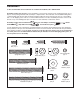
Model No. PFTL49807.0 Serial No. USER'S MANUAL Write the serial number in the space above for future reference. Serial Number Decal QUESTIONS? As a manufacturer, we are committed to providing complete customer satisfaction. If you have questions, or if parts are missing, PLEASE DO NOT CONTACT THE STORE; please contact Customer Care. IMPORTANT: You must note the product model number and serial number (see the drawing above) before contacting us: CALL TOLL-FREE: 1-888-533-1333 Mon.–Fri. 6 a.m.–6 p.m.
TABLE OF CONTENTS WARNING DECAL PLACEMENT . . . . . . . . . . . . . . . . . . . . . . . . . . . . . . . . . . . . . . . . . . . . . . . . . . . . . . . . . . . . . .2 IMPORTANT PRECAUTIONS . . . . . . . . . . . . . . . . . . . . . . . . . . . . . . . . . . . . . . . . . . . . . . . . . . . . . . . . . . . . . . . .3 BEFORE YOU BEGIN . . . . . . . . . . . . . . . . . . . . . . . . . . . . . . . . . . . . . . . . . . . . . . . . . . . . . . . . . . . . . . . . . . . . . .5 ASSEMBLY . . . . . . . . . . . . . .
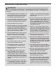
IMPORTANT PRECAUTIONS WARNING: To reduce the risk of serious injury, read all important precautions and instructions in this manual and all warnings on your treadmill before using your treadmill. ICON assumes no responsibility for personal injury or property damage sustained by or through the use of this product. carrying 15 or more amps. No other appliance should be on the same circuit. Do not use an extension cord. 1. Before beginning any exercise program, consult your physician.
20. The pulse sensor is not a medical device. Various factors, including the user's movement, may affect the accuracy of heart rate readings. The pulse sensor is intended only as an exercise aid in determining heart rate trends in general. 24. Never insert any object into any opening on the treadmill. 25. 21. Do not attempt to raise, lower, or move the treadmill until it is properly assembled. (See ASSEMBLY on page 6, and HOW TO FOLD AND MOVE THE TREADMILL on page 21.
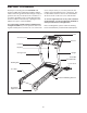
BEFORE YOU BEGIN ual. To help us assist you, note the product model number and serial number before contacting us. The model number and the location of the serial number decal are shown on the front cover of this manual. Thank you for selecting the new PROFORM® 520 Trainer treadmill. The 520 Trainer treadmill combines advanced technology with innovative design to help you get the most from your exercise in the convenience of your home.
ASSEMBLY To hire an authorized service technician to assemble the treadmill, call 1-800-445-2480. Assembly requires two persons. Set the treadmill in a cleared area and remove the packing materials; do not dispose of the packing materials until assembly is completed. Note: The underside of the treadmill walking belt is coated with high-performance lubricant. During shipping, lubricant may be transferred to the top of the walking belt or to the shipping carton.
1. Attach a Wheel (45) to one side of the Base (48) with a Wheel Bolt (14), two Wheel Spacers (44), and a Wheel Nut (35) as shown. Do not overtighten the Wheel Nut; the Wheel should turn freely. 1 45 6 45 44 44 Attach the other Wheel (45) to the other side of the Base (48) in the same way. 6 35 14 37 37 Hole 37 48 Hole Attach the four Base Pads (37) to the Base (48) with four 1 1/2" Screws (6); make sure that the screws are in the indicated holes in the Base. Hole 6 6 Hole 37 2.
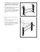
3. Orient the Right Upright (36) as shown, and attach it to the Base (48) with two Upright Bolts (27) and two Upright Star Washers (39); do not tighten the Upright Bolts yet. 3 48 Bend 39 36 27 39 4. Set the Base (48) near the front of the treadmill, with the Power Cord (13) on the Hood (1) as shown. 4 36 Cut the small tie (not shown) holding the Upright Wire (28) in a bundle. 1 13 See the inset drawing.
5. See the left inset drawing. Identify the two Frame Spacers (34). Open the included packet of grease, and apply grease to both sides of both Frame Spacers. Then, identify the outer side of each Frame Spacer. 5 36 91 47 Next, hold a Frame Spacer (34) between the Right Upright (36) and the Lift Frame (59), with the outer side of the Frame Spacer facing the Right Upright.
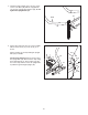
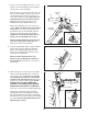
7. Set the console assembly face down on a soft surface to avoid scratching it. Hold a Handrail (18) near the console assembly. 7 Console Wire Next, insert the console wire into the hole in the bottom of the Handrail (18) and out of the indicated square hole. If necessary, grip the connector with needlenose pliers only in the area indicated by the arrow (see the inset drawing). Then, attach the ground wire to the Handrail with a Silver Ground Screw (11).
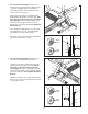
10. Lower the Uprights (31, 36). 10 Side View 32 See the inset drawing. Position the Uprights (31, 36) so that the treadmill Frame (74) is centered between the Uprights. 27 See steps 2, 3, 5, and 6. Firmly tighten the Upright Bolts (27) and the Frame Bolt (32) on each side of the treadmill. Do not overtighten the Frame Bolts. 74 31, 36 View from Above 31 11. Raise the Uprights (31, 36). 36 74 11 Rotate the Left and Right Base Covers (90, 91) 180°. Slide the Base Covers over the Base (48).
. Attach the ground wire on the Upright Wire (28) to the indicated hole in the Base (48) with a Silver Ground Screw (11). 12 Grommet 28 Then, press the indicated grommet into the Right Upright (36). 36 2 Attach the Right Base Cover (91) to the Base (48) with two 3/4" Screws (2). Attach the Left Base Cover (not shown) in the same way. 48 Hole Ground Wire Raise the Uprights (31, 36) to a vertical position. 11 2 91 13. Press the Latch Sleeve (30) into the Left Upright (31).
OPERATION AND ADJUSTMENT THE PRE-LUBRICATED WALKING BELT tric shock. This product is equipped with a cord having an equipment-grounding conductor and a grounding plug. Plug the power cord into a surge suppressor, and plug the surge suppressor into an appropriate outlet that is properly installed and grounded in accordance with all local codes and ordinances. Important: The treadmill is not compatible with GFCI-equipped outlets. Your treadmill features a walking belt coated with highperformance lubricant.
CONSOLE DIAGRAM Clip Key FEATURES OF THE CONSOLE More reliable than conventional pedometers, the treadmill’s step program is highly accurate with most users. The treadmill console offers a selection of features designed to make your workouts more effective. When the manual mode of the console is selected, the speed and incline of the treadmill can be changed with the touch of a button. As you exercise, the console will display continuous exercise feedback.
HOW TO TURN ON THE POWER 3. Select the manual mode. IMPORTANT: If the treadmill has been exposed to cold temperatures, allow it to warm to room temperature before turning on the power. If you do not do this, the console displays or other electrical components may become damaged. Plug in the power cord (see page 13). Next, locate the reset/off circuit breaker on the treadmill frame near the power cord. Switch the circuit breaker to the reset position.
6. Follow your progress with the display. 7. Measure your heart rate if desired. When the manual mode Track is selected, the upper part of the display will show a track that represents 1/4 mile. As you walk or run, indicators will appear in succession around the track until the entire track appears. The track will then disappear and the indicators will again begin to appear in succession. Before using the handgrip pulse sensor, remove the sheets of clear plastic from the metal contacts.
HOW TO USE A DISTANCE PROGRAM Note: To change the speed of the walking belt or the incline of the treadmill at any time during the program, press the Speed or Incline buttons. 1. Insert the key into the console. See HOW TO TURN ON THE POWER on page 15. The left side of the display will show the number of kilometers still to be run every few seconds. 2. Select a distance program. To stop the program at any time, press the Stop button. The time will begin to flash in the display.
3. Press the Start button or the Speed increase button to start the program. HOW TO USE A STEP PROGRAM 1. Insert the key into the console. A moment after the button is pressed, the walking belt will begin to move at 2 mph. Hold the handrails and begin walking. See HOW TO TURN ON THE POWER on page 15. 2. Select a step program. As you exercise, adjust the speed and incline of the treadmill as desired by pressing the Speed and Incline buttons.
HOW TO USE A CALORIE GOAL PROGRAM and the next segment of the profile will begin to flash. If a different speed and incline setting is programmed for the next segment, the speed or incline setting will flash in the display to alert you. 1. Insert the key into the console. See HOW TO TURN ON THE POWER on page 15. If the speed or incline setting for the current segment is too high or too low, you can manually override the setting by pressing the Speed and Incline buttons.
THE INFORMATION MODE The console features an information mode that keeps track of treadmill usage information. The information mode also allows you to select miles or kilometers as the unit of measurement and to turn on and turn off the demo mode. To select the information mode, hold down the Stop button, insert the key into the console, and then release the Stop button.
HOW TO FOLD AND MOVE THE TREADMILL HOW TO FOLD THE TREADMILL FOR STORAGE Before folding the treadmill, adjust the incline to the lowest position. If you do not do this, you may damage the treadmil when you fold it. Next, unplug the power cord. CAUTION: You must be able to safely lift 45 lbs. (20 kg) to raise, lower, or move the treadmill. 1. Hold the metal frame firmly in the location shown by the arrow at the right.
HOW TO LOWER THE TREADMILL FOR USE 1. Hold the treadmill with your right hand as shown. Pull the latch knob to the left and hold it. Pivot the frame down until it is past the latch pin and then slowly release the latch knob. Latch Knob Frame 2. Hold the metal frame firmly with both hands, and lower it to the floor. CAUTION: To decrease the possibility of injury, do not lower the frame by gripping only the plastic foot rails; do not drop the frame to the floor.
TROUBLESHOOTING Most treadmill problems can be solved by following the steps below. Find the symptom that applies, and follow the steps listed. If further assistance is needed, please see the front cover of this manual. PROBLEM: The power does not turn on SOLUTION: a. Make sure that the power cord is plugged into a surge suppressor, and that the surge suppressor is plugged into a properly grounded outlet (see page 13).
PROBLEM: The console displays remain lit when you remove the key from the console SOLUTION: a. The console features a display demo mode, designed to be used if the treadmill is displayed in a store. If the displays remain lit when you remove the key, the demo mode is turned on. To turn off the demo mode, hold down the Stop button for a few seconds. If the displays are still lit, see THE INFORMATION MODE on page 20 to turn off the demo mode. PROBLEM: The walking belt slows when walked on SOLUTION: a.
EXERCISE GUIDELINES WARNING: Before beginning any exercise program, consult your physician. This is especially important for persons over the age of 35 or persons with pre-existing health problems. The pulse sensor is not a medical device. Various factors may affect the accuracy of heart rate readings. The pulse sensor is intended only as an exercise aid in determining heart rate trends in general. These guidelines will help you to plan your exercise program.
SUGGESTED STRETCHES The correct form for several basic stretches is shown at the right. Move slowly as you stretch—never bounce. 1. Toe Touch Stretch Stand with your knees bent slightly and slowly bend forward from your hips. Allow your back and shoulders to relax as you reach down toward your toes as far as possible. Hold for 15 counts, then relax. Repeat 3 times. Stretches: Hamstrings, back of knees and back. 1 2. Hamstring Stretch Sit with one leg extended.
PART LIST—Model No. PFTL49807.0 Key No. Qty.
82 40 81 11 77 4 84 85 38 83 76 69 20 99 43 4 11 82 2 80 77 81 96 79 15 11 70 94 38 69 76 20 4 3 71 68 72 66 76 4 4 99 74 73 75 63 86 24 62 4 64 65 15 70 94 35 67 38 61 66 71 35 49 4 60 86 68 24 76 35 98 2 4 2 38 EXPLODED DRAWING A—Model No. PFTL49807.
EXPLODED DRAWING B—Model No. PFTL49807.
EXPLODED DRAWING C—Model No. PFTL49807.
EXPLODED DRAWING D—Model No. PFTL49807.
ORDERING REPLACEMENT PARTS To order replacement parts, please see the front cover of this manual. To help us assist you, be prepared to provide the following information when contacting us: • the model number and the serial number of the product (see the front cover of this manual) • the name of the product (see the front cover of this manual) • the key number and description of the part(s) (see the PART LIST and the EXPLODED DRAWING near the end of this manual) LIMITED WARRANTY ICON Health & Fitness, Inc.