Model No. PFEVEL74607.0 Serial No. Write the serial number in the space above for reference. Serial Number Decal QUESTIONS? As a manufacturer, we are committed to providing complete customer satisfaction. If you have questions, or if there are missing parts, please contact us: Call: 08457 089 009 Outside UK: 0 (44) 113 3877133 Fax: 0 (44) 113 3877125 E-mail: csuk@iconeurope.com Write: ICON Health & Fitness, Ltd.
TABLE OF CONTENTS WARNING DECAL PLACEMENT . . . . . . . . . . . . . . . . . . . . . . . . . . . . . . . . . . . . . . . . . . . . . . . . . . . . . . . . . . . . . .2 IMPORTANT PRECAUTIONS . . . . . . . . . . . . . . . . . . . . . . . . . . . . . . . . . . . . . . . . . . . . . . . . . . . . . . . . . . . . . . . .3 BEFORE YOU BEGIN . . . . . . . . . . . . . . . . . . . . . . . . . . . . . . . . . . . . . . . . . . . . . . . . . . . . . . . . . . . . . . . . . . . . . .4 ASSEMBLY . . . . . . . . . . . . .
IMPORTANT PRECAUTIONS WARNING: To reduce the risk of serious injury, read all important precautions and instructions in this manual and all warnings on your elliptical exerciser before using your elliptical exerciser. ICON assumes no responsibility for personal injury or property damage sustained by or through the use of this product. 1. Before beginning any exercise program, consult your physician. This is especially important for persons over the age of 35 or persons with pre-existing health problems.
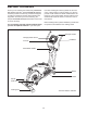
BEFORE YOU BEGIN Thank you for selecting the revolutionary PROFORM® 696 elliptical exerciser. The PROFORM 696 elliptical exerciser provides a wide array of features designed to make your workouts at home more effective and enjoyable—and when you’re not exercising, the unique PROFORM 696 elliptical exerciser can be folded out of the away. tions after reading this manual, please see the front cover of this manual. To help us assist you, note the product model number and serial number before contacting us.
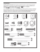
ASSEMBLY Assembly requires two persons. Place all parts of the elliptical exerciser in a cleared area and remove the packing materials. Do not dispose of the packing materials until assembly is completed. In addition to the included tools, assembly requires a Phillips screwdriver , an adjustable wrench , and a rubber mallet . As you assemble the elliptical exerciser, use the drawings below to identify small parts.
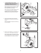
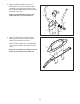
1. To make assembly easier, read the information on page 5 before you begin assembling the elliptical exerciser. 1 82 6 While another person lifts the Base (1), attach the Front Stabilizer (6) to the Base with two M10 x 82mm Button Screws (82). Next, hold the Left and Right Stabilizer Covers (79, 109) around the Base (1). Attach the Stabilizer Covers with six M4 x 16mm Round Head Screws (101) (only three are shown). 79 109 1 2. Remove the indicated screw and bracket from the Base (1).
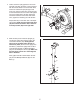
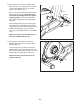
4. Hold a Crank Arm (36) against the left Crank Hub (38), and align the holes in the Crank Arm with the unused holes in the Crank Hub. Next, insert four Hub Screws (87) through a Hub Cover (75) into the Crank Arm, and finger tighten the Hub Screws into the Crank Hub. Tighten one of the Hub Screws, and then tighten the Hub Screw farthest from the first Hub Screw. Then, tighten the remaining two Hub Screws. 4 98 36 38 Repeat this step on the other side of the elliptical exerciser.
6. Orient the Left and Right Upright Covers (17, 18) as shown. Attach the Upright Covers around the Upright (3) with four M4 x 16mm Round Head Screws (101). 6 101 3 17 101 18 7. Apply a generous amount of the included grease to the Pivot Axle (74), and then apply a small amount of grease to two 22mm x 16mm Wave Washers (111). Next, insert the Pivot Axle through the Upright (3). 7 84 Place a 22mm x 16mm Wave Washer (111) on the left end of the Pivot Axle (74).
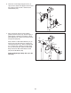
8. Identify the Right Handlebar (9), which is marked with an “R” sticker. Attach the Right Handlebar to the Right Upper Body Arm (12) with three M8 x 38mm Button Screws (4) and a Handlebar Cover (19). 8 Attach the Left Handlebar (8) to the Left Upper Body Arm (11) in the same way. 8 9 19 12 11 9. Identify the Right Pedal (15) and the Right Pedal Leg (16), which are marked with “R” stickers, and orient them as shown.
. Apply grease to the axle on the Right Upper Body Arm (12). Then, apply grease to a 23mm x 19mm Wave Washer (97) and to an M8 x 23mm x 1mm Washer (112). 10 Slide an Upper Body Arm Spacer (62) onto the Right Upper Body Arm (12); make sure that the flat side of the Upper Body Arm Spacer is facing outward. Then, place the 23mm x 19mm Wave Washer (97) on the Right Upper Body Arm. 11 12 14 Grease 62 97 16 112 Slide the Right Pedal Leg (16) onto the Right Upper Body Arm (12).
12. The Console (5) can be operated with four 1.5V “D” batteries; alkaline batteries are recommended. IMPORTANT: If the elliptical exerciser has been exposed to cold temperatures, allow it to warm to room temperature before inserting batteries into the Console. If you do not do this, the console displays or other electronic components may become damaged. Press the tab on the battery cover, and remove the battery cover. Next, insert four batteries into the Console.
HOW TO USE THE ELLIPTICAL EXERCISER HOW TO FOLD AND UNFOLD THE ELLIPTICAL EXERCISER HOW TO MOVE THE ELLIPTICAL EXERCISER To move the elliptical exerciser, first fold it as described at the left. Next, stand in front of the elliptical exerciser, hold the transport handle on the upright, and place one foot against the center of the front stabilizer. Pull the transport handle until the elliptical exerciser will roll on the front wheels.
HOW TO EXERCISE ON THE ELLIPTICAL EXERCISER Handlebars To mount the elliptical exerciser, hold the handlebars and step onto the pedal that is in the lowest position. Next, step onto the other pedal. Push the pedals until they begin to move with a continuous motion. Note: The pedal discs can turn in either direction. It is recommended that you turn the pedal discs in the direction shown by the arrow below; however, for variety, you can turn the pedal discs in the opposite direction.
HOW TO LEVEL THE ELLIPTICAL EXERCISER If the elliptical exerciser rocks slightly on your floor during use, turn one or both of the leveling feet beneath the rear stabilizer until the rocking motion is eliminated.
CONSOLE DIAGRAM FEATURES OF THE CONSOLE prompt you to increase or decrease your pedaling pace while guiding you through an effective workout. The advanced console offers an array of features designed to make your workouts more effective and enjoyable. When you use the manual mode of the console, you can change the resistance of the pedals with the touch of a button. As you exercise, the console will provide continuous exercise feedback.
HOW TO USE THE MANUAL MODE 4. Follow your progress with the displays. Note: If there is a sheet of clear plastic on the face of the console, remove the plastic. The upper right display can show the elapsed time, the approximate number of calories you have burned, and the the distance (total revolutions) you have pedaled. The display will change modes every few seconds. 1. Press any button on the console or begin pedaling to turn on the console.
5. Measure your heart rate if desired. If your heart rate is not shown, make sure that your hands are positioned as described. Be careful not to move your hands excessively or to squeeze the metal contacts tightly. For optimal performance, clean the metal contacts using a soft cloth; never use alcohol, abrasives, or chemicals to clean the contacts. If there are sheets of clear Contacts plastic on the metal contacts on the handgrip pulse sensor, remove the plastic.
HOW TO USE A PRESET WORKOUT indicator lights, increase your pace; when a right indicator lights, decrease your pace. When the center indicator lights, maintain your current pace. 1. Press any button on the console or begin pedaling to turn on the console. See step 1 on page 16. 2. Select a preset workout. IMPORTANT: The target pacer is intended only to provide a goal. Make sure to pedal at a pace that is comfortable for you.
MAINTENANCE AND TROUBLESHOOTING HOW TO ADJUST THE REED SWITCH Inspect and tighten all parts of the elliptical exerciser regularly. Replace any worn parts immediately. If the console does not display correct feedback, the reed switch should be adjusted. First, see step 11 on page 10 and remove the link arms. Next, see step 4 on page 7 and remove the crank arms. To clean the elliptical exerciser, use a damp cloth and a small amount of mild soap.
HOW TO ADJUST THE BELT Next, tighten the M8 x 35mm Screw (96) until the Belt 51 (51) is tight. Then, reattach the side shields, the crank arms, and the link arms. Note: If you have questions as 96 to which screw should be in which hole, see EXPLODED DRAWING B on page 27 and the PART LIST on page 24. If you can feel the pedals slip while you are pedaling, even when the resistance of the pedals is at the highest setting, the Belt (51) may need to be adjusted.
EXERCISE GUIDELINES WARNING: Before beginning Burning Fat—To burn fat effectively, you must exercise at a low intensity level for a sustained period of time. During the first few minutes of exercise, your body uses carbohydrate calories for energy. Only after the first few minutes of exercise does your body begin to use stored fat calories for energy. If your goal is to burn fat, adjust the intensity of your exercise until your heart rate is near the lowest number in your training zone.
SUGGESTED STRETCHES The correct form for several basic stretches is shown at the right. Move slowly as you stretch—never bounce. 1 1. Toe Touch Stretch Stand with your knees bent slightly and slowly bend forward from your hips. Allow your back and shoulders to relax as you reach down toward your toes as far as possible. Hold for 15 counts, then relax. Repeat 3 times. Stretches: Hamstrings, back of knees and back. 2 2. Hamstring Stretch Sit with one leg extended.
NOTES 23
PART LIST—Model No. PFEVEL74607.0 Key No. Qty. 1 2 3 4 5 6 7 8 9 10 11 12 13 14 15 16 17 18 19 20 21 22 23 24 25 26 27 28 29 30 31 32 33 34 35 36 37 38 39 40 41 42 43 44 45 46 47 48 49 50 1 1 1 6 1 1 1 1 1 2 1 1 1 1 1 1 1 1 2 2 2 4 2 2 2 1 2 1 1 2 2 2 4 1 2 2 2 2 1 1 2 4 2 2 1 1 2 1 1 1 Description Key No. Qty.
Key No. Qty. 101 102 103 104 105 106 107 108 109 110 14 4 28 8 2 2 4 2 1 4 Description Key No. Qty.
88 78 22 19 71 4 4 8 20 21 22 104 63 113 10 110 61 60 65 14 35 112 13 88 84 88 104 63 68 116 32 115 31 73 84 62 116 79 35 11 64 108 97 26 101 33 33 48 49 74 34 88 84 23 1 84 78 90 101 89 84 90 90 80 71 25 89 25 88 78 20 21 22 15 108 22 63 113 18 101 111 23 105 3 30 101 109 6 81 101 82 66 17 105 111 30 5 104 32 101 12 66 63 16 73 84 104 88 64 97 62 9 19 4 4 31 110 112 115 33 10 EXPLODED DRAWING A—Model No
110 106 27 87 75 42 112 44 76 38 47 86 43 45 97 42 44 99 37 46 107 100 40 36 98 47 98 103 103 103 103 103 41 103 55 55 27 103 39 24 28 38 103 41 86 83 102 70 36 58 96 102 50 2 27 103 103 7 103 85 37 59 57 99 113 75 69 43 97 24 42 72 112 42 107 95 114 67 113 103 94 91 103 78 51 110 106 56 53 107 76 87 77 54 29 77 52 100 93 103 103 94 94 92 EXPLODED DRAWING B—Model No. PFEVEL74607.
ORDERING REPLACEMENT PARTS To order replacement parts, please see the front cover of this manual. To help us assist you, be prepared to provide the following information when contacting us: • the model number and serial number of the product (see the front cover of this manual) • the name of the product (see the front cover of this manual) • the key number and description of the replacement part(s) (see the PART LIST and the EXPLODED DRAWING near the end of this manual) Part No.