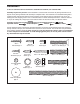
www.proform.com Model No. PFTL57908.2 Serial No. Write the serial number in the space above for reference. Serial Number Decal QUESTIONS? If you have questions, or if parts are damaged or missing, DO NOT CONTACT THE STORE; please contact Customer Care. IMPORTANT: Please register this product (see the limited warranty on the back cover of this manual) before contacting Customer Care. 1-888-533-1333 CALL TOLL-FREE: Mon.–Fri. 6 a.m.–6 p.m. MT Sat. 8 a.m.–4 p.m. MT ON THE WEB: www.proformservice.
TABLE OF CONTENTS WARNING DECAL PLACEMENT . . . . . . . . . . . . . . . . . . . . . . . . . . . . . . . . . . . . . . . . . . . . . . . . . . . . . . . . . . . . . .2 IMPORTANT PRECAUTIONS . . . . . . . . . . . . . . . . . . . . . . . . . . . . . . . . . . . . . . . . . . . . . . . . . . . . . . . . . . . . . . . .3 BEFORE YOU BEGIN . . . . . . . . . . . . . . . . . . . . . . . . . . . . . . . . . . . . . . . . . . . . . . . . . . . . . . . . . . . . . . . . . . . . . .5 ASSEMBLY . . . . . . . . . . . . .
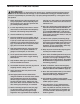
IMPORTANT PRECAUTIONS WARNING: To reduce the risk of serious injury, read all important precautions and instructions in this manual and all warnings on your treadmill before using your treadmill. ICON assumes no responsibility for personal injury or property damage sustained by or through the use of this product. 1. Before beginning any exercise program, consult your physician. This is especially important for persons over age 35 or persons with pre-existing health problems. carrying 15 or more amps.
24. Inspect and properly tighten all parts of the treadmill regularly. 20. Never leave the treadmill unattended while it is running. Always remove the key, unplug the power cord, and switch the reset/off circuit breaker to the off position when the treadmill is not in use. (See the drawing on page 5 for the location of the circuit breaker.) 25. 21. Do not attempt to raise, lower, or move the treadmill until it is properly assembled.
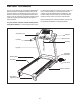
BEFORE YOU BEGIN Thank you for selecting the revolutionary PROFORM® 580 CS treadmill. The 580 CS treadmill offers an impressive selection of features designed to make your workouts at home more enjoyable and effective. And when youʼre not exercising, the unique treadmill can be folded up, requiring less than half the floor space of other treadmills. ing this manual, please see the front cover of this manual. To help us assist you, note the product model number and serial number before contacting us.
ASSEMBLY To hire an authorized service technician to assemble the treadmill, call 1-800-445-2480. Assembly requires two persons. Set the treadmill in a cleared area and remove all packing materials. Do not dispose of the packing materials until assembly is completed. Note: The underside of the treadmill walking belt is coated with high-performance lubricant. During shipping, some lubricant may be transferred to the top of the walking belt or the shipping carton.
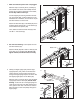
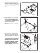
1. Make sure that the power cord is unplugged. 1 With the help of a second person, carefully tip the treadmill onto its left side. Partially fold the Frame (48) so that the treadmill is more stable; do not fully fold the Frame yet. Hole 91 97 96 Cut the shipping tie securing the Wire Harness (91) to the Base (96). Locate a plastic tie in the indicated hole in the Base, and use the tie to pull the Wire Harness out of the hole.
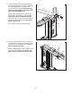
4. Hold a Bolt Spacer (95) inside the lower end of the Right Upright (92). Insert a 3/8" x 4" Bolt (8) with a 3/8" Star Washer (11) into the Right Upright and the Bolt Spacer. Repeat this step with a second Bolt Spacer (95), 3/8" x 4" Bolt (8), and 3/8" Star Washer (11). 4 8 92 11 91 Hold the Right Upright Spacer (100) and the Right Upright (92) against the Base (96). Be careful not to pinch the Wire Harness (91).
6. Hold a Bolt Spacer (95) inside the lower end of the Left Upright (77). Insert a 3/8" x 4" Bolt (8) with a 3/8" Star Washer (11) into the Left Upright and the Bolt Spacer. Repeat this step with a second Bolt Spacer (95), 3/8" x 4" Bolt (8), and 3/8" Star Washer (11). 6 8 77 11 Hold the Left Upright Spacer (94) and the Left Upright (77) against the Base (96). Tighten the 3/8" x 4" Bolts (8) until the heads of the Bolts touch the Left Upright; do not fully tighten the Bolts yet.
9. Set the console assembly face down on a soft surface to avoid scratching the console assembly. Remove the two #8 x 3/4" Screws (1). Lift off the Pulse Bar (90). Save the Pulse Bar and the two Screws for assembly steps 10 and 12. 9 1 90 Console Assembly 10. Set the Pulse Bar (90) on the Left and Right Uprights (77, 92). Attach the Pulse Bar with four #10 x 3/4" Screws (4) and four #10 Star Washers (12). Start all four Screws before firmly tightening any of them.
12. Set the console assembly on the Left and Right Uprights (77, 92). Be careful not to pinch any wires. 12 Console Assembly Attach the console assembly to the Pulse Bar (90) with six #8 x 3/4" Screws (1). Start all six Screws before firmly tightening any of them. 92 13. Identify the Right Handrail Cover (55), which is marked with a sticker. Slide the Right Handrail Cover onto the right Handrail (80).
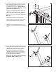
15. Raise the Frame (48) to the position shown. Have a second person hold the Frame until this step is completed. 15 48 10 Orient the Storage Latch (45) so that the large barrel and the Latch Knob (46) are in the positions shown. Attach the upper end of the Storage Latch (45) to the bracket on the Frame (48) with a 3/8" x 2" Bolt (9) and a 3/8" Nut (10). 9 45 46 Attach the lower end of the Storage Latch (45) to the Base (96) with a 3/8" x 1 3/4" Bolt (7).
OPERATION AND ADJUSTMENT THE PRE-LUBRICATED WALKING BELT Your treadmill features a walking belt coated with highperformance lubricant. IMPORTANT: Never apply silicone spray or other substances to the walking belt or the walking platform. Such substances will deteriorate the walking belt and cause excessive wear. HOW TO PLUG IN THE POWER CORD DANGER: Improper connection of the equipment-grounding conductor can result in an increased risk of electric shock.
CONSOLE DIAGRAM Clip Key FEATURES OF THE CONSOLE The treadmill console offers an impressive array of features designed to help you get the most from your workouts. When you use the manual mode of the console, you can change the speed and incline of the treadmill with the touch of a button. As you exercise, the console will display continuous exercise feedback. You can even measure your heart rate using the builtin handgrip pulse sensor. In addition, the console features twelve preset programs.
HOW TO TURN ON THE POWER IMPORTANT: If the treadmill has been exposed to cold temperatures, allow it to warm to room temperature before turning on the power. If you do not do this, you may damage the console displays or other electrical components. Plug in the power cord (see page 13). Next, locate the reset/off circuit breaker on the treadmill frame near the power cord. Switch the circuit breaker to the reset position.
5. Follow your progress with the matrix and the displays. To review specific information, press the Display button repeatedly until the displays show the information that you are most interested in viewing. The matrix— When the manual mode is selected, the matrix will show a 1/4Track mile track. As you walk or run, the indicators around the track will light in succession until the entire track is lit. The track will then disappear and the indicators will again begin to light in succession. 6.
HOW TO USE A PERSONAL TRAINER QUICK PROGRAM resents the current segment of the program. The height of the flashing segment indicates the speed setting for the current segment. At the end of each segment, a series of tones will sound and the next segment of the profile will begin to flash. If a different speed and incline setting is programmed for the next segment, the speed or incline setting will flash in the display to alert you.
HOW TO CREATE YOUR OWN QUICK PROGRAM and Power Incline buttons. Every few times a Quick Speed button is Current Segment pressed, an additional indicator will appear or disappear in the current segment column. 1. Insert the key into the console. See HOW TO TURN ON THE POWER on page 15. 2. Select a custom quick program. To select a custom quick program, press one of the two Create Your Own Quick Programs buttons.
HOW TO USE YOUR OWN QUICK PROGRAM and incline setting is programmed for the next segment, the speed or incline setting will flash in the display to alert you. The treadmill will then automatically adjust to the speed and/or incline setting for the next segment. 1. Insert the key into the console. See HOW TO TURN ON THE POWER on page 15. The program will continue in this way until the last segment of the profile flashes in the current segment column and the last segment ends.
THE INFORMATION MODE The console features an information mode that keeps track of the total number of miles that the walking belt has moved and the total number of hours that the treadmill has been operated. The information mode also allows you to select miles or kilometers as the unit of measurement and to turn on and turn off the display demo mode. To select the information mode, hold down the Stop button while inserting the key into the console.
HOW TO FOLD AND MOVE THE TREADMILL HOW TO FOLD THE TREADMILL FOR STORAGE Before folding the treadmill, adjust the incline to the lowest position. If you do not do this, you may damage the treadmill when you fold it. Remove the key and unplug the power cord. CAUTION: You must be able to safely lift 45 lbs. (20 kg) to raise, lower, or move the treadmill. 1 1. Hold the metal frame firmly in the location shown by the arrow at the right.
TROUBLESHOOTING Most treadmill problems can be solved by following the steps below. Find the symptom that applies, and follow the steps listed. If further assistance is needed, please see the front cover of this manual. PROBLEM: The power does not turn on SOLUTION: a. Make sure that the power cord is plugged into a surge suppressor, and that the surge suppressor is plugged into a properly grounded outlet (see page 13).
Remove the three #8 x 3/4" Screws (1) and carefully pivot the Motor Hood (58) off. 58 Locate the Reed Switch (65) and the Magnet (40) on the left side of the Pulley (41). Turn the Pulley until the Magnet is aligned with the Reed Switch. Make sure that the gap between the Magnet and the Reed Switch is about 1/8 in. (3 mm). If necessary, loosen the #8 x 3/4" Pan Head Screw (15), move the Reed Switch slightly, and then retighten the Pan Head Screw.
PROBLEM: The walking belt is off-center or slips when walked on SOLUTION: a. If the walking belt is off-center, first remove the key and UNPLUG THE POWER CORD. If the walking belt has shifted to the left, use the hex key to turn the left idler roller bolt clockwise 1/2 of a turn; if the walking belt has shifted to the right, turn the bolt counterclockwise 1/2 of a turn. Be careful not to overtighten the walking belt. Then, plug in the power cord, insert the key, and run the treadmill for a few minutes.
EXERCISE GUIDELINES WARNING: Before beginning this Burning Fat—To burn fat effectively, you must exercise at a low intensity level for a sustained period of time. During the first few minutes of exercise, your body uses carbohydrate calories for energy. Only after the first few minutes of exercise does your body begin to use stored fat calories for energy. If your goal is to burn fat, adjust the intensity of your exercise until your heart rate is near the lowest number in your training zone.
PART LIST—Model No. PFTL57908.2 To locate the parts listed below, see the EXPLODED DRAWING near the end of this manual. Key No. Qty. 1 2 3 4 5 6 7 8 9 10 11 12 13 14 15 16 17 18 19 20 21 22 23 24 25 26 27 28 29 30 31 32 33 34 35 36 37 38 39 40 41 42 43 44 45 46 47 48 49 50 19 4 6 4 4 4 1 4 3 3 4 4 7 3 10 2 2 2 2 1 1 2 7 8 2 4 2 2 4 4 3 2 1 1 2 2 2 2 1 1 1 1 1 1 1 1 1 1 2 1 Description Key No. Qty.
Key No. Qty. 101 102 103 * 2 1 1 – Description Key No. Qty. Caution Decal #8 x 1/2" Console Ground Screw Lift Motor Wire 8" Blue Wire, M/F * * * * – – – – Description 10" Blue Wire, 2F 12" Red Wire, M/F 10" Black Wire, M/F Userʼs Manual Note: Specifications are subject to change without notice. For information about ordering replacement parts, see the back cover of this manual. *These parts are not illustrated.
19 28 27 3 49 24 23 52 15 54 30 56 17 34 24 19 33 23 28 27 35 32 3 15 15 49 30 26 36 50 51 17 24 30 24 24 16 48 42 10 47 37 38 24 15 43 41 40 9 46 35 24 15 45 26 16 32 36 30 39 24 37 38 44 7 EXPLODED DRAWING A—Model No. PFTL57908.
EXPLODED DRAWING B—Model No. PFTL57908.
EXPLODED DRAWING C—Model No. PFTL57908.
EXPLODED DRAWING D—Model No. PFTL57908.
ORDERING REPLACEMENT PARTS To order replacement parts, please see the front cover of this manual.