Model No. PFCCEX53912.0 Serial No. Write the serial number in the space above for reference. USER’S MANUAL Serial Number Decal ACTIVATE YOUR WARRANTY To register your product and activate your warranty today, contact Customer Service. CUSTOMER SERVICE Call toll-free 1-888-936-4266 Mon.–Fri. 7:30 a.m.–4:30 p.m. ET (excluding holidays) or email us at customerservice@iconcanada.ca Please do not contact the store. CAUTION Read all precautions and instructions in this manual before using this equipment.
TABLE OF CONTENTS WARNING DECAL PLACEMENT . . . . . . . . . . . . . . . . . . . . . . . . . . . . . . . . . . . . . . . . . . . . . . . . . . . . . . . . . . . . . . .2 IMPORTANT PRECAUTIONS. . . . . . . . . . . . . . . . . . . . . . . . . . . . . . . . . . . . . . . . . . . . . . . . . . . . . . . . . . . . . . . . . . 3 BEFORE YOU BEGIN. . . . . . . . . . . . . . . . . . . . . . . . . . . . . . . . . . . . . . . . . . . . . . . . . . . . . . . . . . . . . . . . . . . . . . . .6 PART IDENTIFICATION CHART.
IMPORTANT PRECAUTIONS WARNING: To reduce the risk of serious injury, read all important precautions and instructions in this manual and all warnings on your exercise bike before using your exercise bike. ICON assumes no responsibility for personal injury or property damage sustained by or through the use of this product. 1. It is the responsibility of the owner to ensure that all users of the exercise bike are adequately informed of all precautions. 9.
Your new fitness equipment represents a significant investment in your health. Protect your investment now from unexpected mechanical or electrical failures for up to five years.
BEFORE YOU BEGIN Thank you for selecting the revolutionary PROFORM® 6.0 ES exercise bike. Cycling is an effective exercise for increasing cardiovascular fitness, building endurance, and toning the body. The 6.0 ES exercise bike provides an impressive selection of features designed to make your workouts at home more effective and enjoyable. reading this manual, please see the front cover of this manual. To help us assist you, note the product model number and serial number before contacting us.
PART IDENTIFICATION CHART Use the drawings below to identify the small parts needed for assembly. The number in parentheses below each drawing is the key number of the part, from the PART LIST near the end of this manual. The number following the key number is the quantity needed for assembly. Note: If a part is not in the hardware kit, check to see if it has been preassembled. Extra parts may be included.
ASSEMBLY • Assembly requires two persons. • In addition to the included tool(s), assembly requires the following tools: • Place all parts in a cleared area and remove the packing materials. Do not dispose of the packing materials until you finish all assembly steps. one Phillips screwdriver one adjustable wrench • Left parts are marked “L” or “Left” and right parts are marked “R” or “Right.” Assembly may be easier if you have a set of wrenches. To avoid damaging parts, do not use power tools.
3. Set a sturdy piece of packing material under the rear of the Frame (1). Have a second person hold the Frame to prevent it from tipping while you complete this step. Orient the Rear Stabilizer (3) so that the welded tubes are facing away from the Frame (1). Attach the Rear Stabilizer (3) to the Frame (1) with two M10 x 95mm Screws (62). Remove the packing material. 3 3 1 62 4. Slide the Shield Cover (5) upward onto the Upright (4).
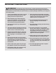
5. Locate the wire tie inside the Upright (4). Then, locate the Main Wire (76) and the Frame Pulse Wire (75) inside the Frame (1). 5 Wire Tie 5 Tie the lower end of the wire tie to the ends of the Main Wire (76) and the Frame Pulse Wire (75). Wire Tie Then, pull the other end of the wire tie upward until the Main Wire (76) and the Frame Pulse Wire (75) are routed through the Upright (4).
7. Insert the Main Wire (76) and the Frame Pulse Wire (75) upward through the indicated hole in the Upright (4). 7 4 75 76 8. While a second person holds the Console (7) near the Upright (4), connect the wires on the Console to the Main Wire (76) and the Frame Pulse Wire (75). Insert the excess wire into the Upright (4) or into the Console (7). Tip: Avoid pinching the wires. Attach the Console (7) to the Upright (4) with four M4 x 16mm Screws (56).
9. Identify the Right and Left Handlebar Covers (8, 9). 9 9 90 Attach the Right and Left Handlebar Covers (8, 9) around the Handlebar (6) and the Upright (4) with four M4 x 22mm Screws (90). 8 6 90 4 10. Attach the Seat (15) to the Seat Carriage (11) with four M6 x 50mm Screws (65) and four M6 Washers (66) (only two of each are shown). Note: The Screws and Washers may be preattached to the underside of the Seat.
11. Attach the Backrest (13) to the Seat Carriage (11) with five M8 x 16mm Screws (60) and five M8 Split Washers (61). 11 Tip: It may be helpful to adjust the seat during this step. See HOW TO ADJUST THE SEAT on page 16. 13 61 11 60 12. Identify and orient the Pulse Bar (12) so that the Pulse Grips (41) face upward. 12 Avoid pinching the Pulse Bar Pulse Wire (72) Tip: Avoid pinching the Pulse Bar Pulse Wire (72).
13. Plug the Pulse Bar Pulse Wire (72) into the Frame Pulse Receptacle (75) located in the Left Seat Shield (24). 13 75 72 24 14. Identify the Right Pedal (16). Using an adjustable wrench, firmly tighten the Right Pedal (16) clockwise into the Right Crank Arm (17). Firmly tighten the Left Pedal (not shown) counterclockwise into the Left Crank Arm (not shown). Adjust the right strap to the desired position, and press the ends of the strap onto the tabs on the Right Pedal (16).
. Plug the Power Adapter (49) into the receptacle on the frame of the exercise bike. To plug the Power Adapter into an outlet, see HOW TO PLUG IN THE POWER ADAPTER on page 16. 15 49 16. After the exercise bike is assembled, inspect it to make sure that it is assembled correctly and that it functions properly. Make sure that all parts are properly tightened before you use the exercise bike. Note: Extra parts may be included. Place a mat beneath the exercise bike to protect the floor.
HOW TO USE THE EXERCISE BIKE HOW TO PLUG IN THE POWER ADAPTER HOW TO ADJUST THE PEDAL STRAPS IMPORTANT: If the exercise bike has been exposed to cold temperatures, allow it to warm to room temperature before plugging in the power adapter. If you do not do this, you may damage the console displays or other electronic components. To adjust the pedal straps, first pull the ends of the straps off the tabs on the pedals.
CONSOLE DIAGRAM FEATURES OF THE CONSOLE through an optional iFit module. With the iFit mode, you can download personalized workouts, create your own workouts, track your workout results, race against other iFit users, and access many other features. To purchase an iFit module at any time, go to www.iFit.com or call the telephone number on the front cover of this manual. The advanced console offers an array of features designed to make your workouts more effective and enjoyable.
HOW TO USE THE MANUAL MODE Distance (Dist.)—This display mode will show the distance that you have pedaled in miles or kilometers. 1. Begin pedaling or press any button on the console to turn on the console. When you turn on the console, the display will turn on. The console will then be ready for use. Pulse—This display mode will show your heart rate when you use the handgrip heart rate monitor (see step 5). 2. Select the manual mode.
Press the Home button to return to the default menu (see HOW TO CHANGE CONSOLE SETTINGS on page 24 to set the default menu). If necessary, press the Home button again. When your pulse is detected, a heart symbol in the calorie display will flash each time your heart beats, one or two dashes will appear, and then your heart rate will be shown. For the most accurate heart rate reading, hold the contacts for at least 15 seconds.
HOW TO USE AN ONBOARD WORKOUT the profile will begin to flash. If a different resistance level and/or target speed is programmed for the next segment, the resistance level and/or target speed will appear in the display for a few seconds to alert you. The resistance of the pedals will then change. 1. Begin pedaling or press any button on the console to turn on the console. When you turn on the console, the display will turn on. The console will then be ready for use.
HOW TO USE A SET-A-GOAL WORKOUT Note: If you manually change the resistance during a calorie goal workout, the length of the workout will adjust automatically to ensure that you meet your calorie goal. 1. Begin pedaling or press any button on the console to turn on the console. Note: The calorie goal is an estimate of the number of calories that you will burn during the workout. The actual number of calories that you burn will depend on various factors such as your weight.
HOW TO USE AN IFIT WORKOUT Press the Map button, the Train button, or the Lose Wt. button to download the next workout of that type in your schedule. 1. Begin pedaling or press any button on the console to turn on the console. Press the Compete button to compete in a race that you have previously scheduled. When you turn on the console, the display will turn on. The console will then be ready for use. Press the Track button to re-run a recent iFit workout from your schedule.
6. Follow your progress with the display. 8. When you are finished exercising, the console will turn off automatically. See step 4 on page 18. The My Trail tab will show a map of the trail you are walking or running or it will show a track and the number of laps you complete. For more information on the iFit mode, go to www.iFit.com. IMPORTANT: To satisfy exposure compliance requirements, the antenna and transmitter in the iFit module must be at least 8 in.
HOW TO CHANGE CONSOLE SETTINGS If no module is connected, the display will show the words NO IFIT MODULE. If no module is connected, go to step 10. The console features a user mode that allows you to view usage information, select a unit of measurement, and adjust the contrast level of the display. 6. Select an audio setting for the voice of the personal trainer if desired.
MAINTENANCE AND TROUBLESHOOTING Inspect and tighten all parts of the exercise bike regularly. Replace any worn parts immediately. 70 To clean the exercise bike, use a damp cloth and a small amount of mild soap. IMPORTANT: To avoid damage to the console, keep liquids away from the console and keep the console out of direct sunlight. 29 46 5 CONSOLE TROUBLESHOOTING If lines appear in the console display, see step 4 on page 24 and adjust the contrast level of the display.
HOW TO ADJUST THE DRIVE BELT If the pedals slip while you are pedaling, even while the resistance is adjusted to the highest setting, the drive belt may need to be adjusted. Then, remove all the screws from the Left and Right Front Shields (22, not shown); there are three sizes of screws in the Front Shields—note which size of screw you remove from each hole. Then, gently pull the Right Front Shield away from the frame. To adjust the drive belt, first unplug the power adapter.
EXERCISE GUIDELINES Burning Fat—To burn fat effectively, you must exercise at a low intensity level for a sustained period of time. During the first few minutes of exercise, your body uses carbohydrate calories for energy. Only after the first few minutes of exercise does your body begin to use stored fat calories for energy. If your goal is to burn fat, adjust the intensity of your exercise until your heart rate is near the lowest number in your training zone.
SUGGESTED STRETCHES The correct form for several basic stretches is shown at the right. Move slowly as you stretch; never bounce. 1. Toe Touch Stretch Stand with your knees bent slightly and slowly bend forward from your hips. Allow your back and shoulders to relax as you reach down toward your toes as far as possible. Hold for 15 counts, then relax. Repeat 3 times. Stretches: Hamstrings, back of knees and back. 1 2. Hamstring Stretch Sit with one leg extended.
PART LIST Model No. PFCCEX53912.0 R0113A Key No. Qty. Description Key No. Qty.
50 40 50 50 63 39 66 69 50 66 60 69 61 61 12 28 66 50 38 50 69 30 56 66 69 62 50 6 3 72 88 79 31 35 70 30 46 50 18 41 50 83 32 66 33 56 57 83 11 66 50 67 7 40 38 61 37 39 61 56 41 42 59 36 45 42 48 82 56 19 60 61 87 61 60 64 60 56 75 1 55 79 5 68 60 90 89 31 84 85 47 86 82 61 43 60 44 61 79 28 61 4 56 85 79 27 77 51 61 85 29 52 79 78 85 74 81 34 43 44 74 56 79 61 29 20 9 2 58 8 73 17 26 64 59 62 4
79 79 80 80 79 79 24 79 14 71 71 79 23 10 31 79 66 79 13 79 65 54 65 66 15 79 53 54 22 54 79 79 21 25 79 EXPLODED DRAWING B Model No. PFCCEX53912.
ORDERING REPLACEMENT PARTS To order replacement parts, please see the front cover of this manual.