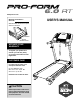
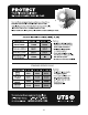
www.proform.com Model No. PFTL39511.3 Serial No. Write the serial number in the space above for reference. Serial Number Decal ACTIVATE YOUR WARRANTY To register your product and activate your warranty today, go to www.proformservice.com/ registration. CUSTOMER CARE For service at any time, go to www.proformservice.com. Or call 1-888-533-1333 Mon.–Fri. 6 a.m.–6 p.m. MT Sat. 8 a.m.–4 p.m. MT Please do not contact the store.
TABLE OF CONTENTS WARNING DECAL PLACEMENT . . . . . . . . . . . . . . . . . . . . . . . . . . . . . . . . . . . . . . . . . . . . . . . . . . . . . . . . . . . . . . . 2 IMPORTANT PRECAUTIONS . . . . . . . . . . . . . . . . . . . . . . . . . . . . . . . . . . . . . . . . . . . . . . . . . . . . . . . . . . . . . . . . . . 3 BEFORE YOU BEGIN. . . . . . . . . . . . . . . . . . . . . . . . . . . . . . . . . . . . . . . . . . . . . . . . . . . . . . . . . . . . . . . . . . . . . . . .
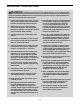
IMPORTANT PRECAUTIONS WARNING: To reduce the risk of burns, fire, electric shock, or injury to persons, read all important precautions and instructions in this manual and all warnings on your treadmill before using your treadmill. ICON assumes no responsibility for personal injury or property damage sustained by or through the use of this product. 1. It is the responsibility of the owner to ensure that all users of this treadmill are adequately informed of all warnings and precautions. 12.
20. The heart rate monitor is not a medical device. Various factors, including the user’s movement, may affect the accuracy of heart rate readings. The heart rate monitor is intended only as an exercise aid in determining heart rate trends in general. 24. Never insert any object into any opening on the treadmill. 25. Inspect and properly tighten all parts of the treadmill regularly. 26. 21. Never leave the treadmill unattended while it is running.
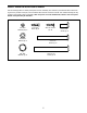
STANDARD SERVICE PLANS all 5
BEFORE YOU BEGIN Thank you for selecting the new PROFORM® 6.0 RT treadmill. The 6.0 RT treadmill provides an impressive selection of features designed to make your workouts at home more effective and enjoyable. manual. To help us assist you, note the product model number and serial number before contacting us. The model number and the location of the serial number decal are shown on the front cover of this manual. For your benefit, read this manual carefully before you use the treadmill.
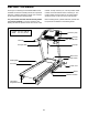
PART IDENTIFICATION CHART Use the drawings below to identify small parts used for assembly. The number in parentheses below each drawing is the key number of the part, from the PART LIST near the end of this manual. The number following the key number is the quantity used for assembly. Note: If a part is not in the hardware kit, check to see if it is preattached. Extra parts may be included.
ASSEMBLY • To hire a service technician to assemble this product in your home, call 1-800-445-2480. • Left parts are marked “L” or “Left” and right parts are marked “R” or “Right.” • Assembly requires two persons. • To identify small parts, see page 7. • Place all parts in a cleared area and remove the packing materials. Do not dispose of the packing materials until you nish all assembly steps.
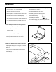
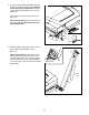
3. Locate the Upright Wire (63) bundled between the Base (74) and the Belly Pan (52). Remove all ties securing the Upright Wire. Route the Upright Wire into the Base and out of the indicated hole. 3 Press a Base Cap (70) into each side of the Base (74). See the inset drawing. Cut the plastic tie near the Upright Wire (63). Be careful not to damage the Upright Wire. 52 74 Ties 63 4. Identify the Right Upright (76). Have a second person hold the Right Upright near the Base (74).
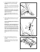
5. Hold the Right Upright (76) against the Base (74). Be careful not to pinch the Upright Wire (63). 5 76 Insert a 3/8" x 3 1/4" Screw (2) with a 3/8" Star Washer (3) into the top hole in the Right Upright (76). Then, partially tighten the Screw into the Base (74). Partially tighten two more 3/8" x 3 1/4" Screws (2) with two 3/8" Star Washers (3) into the Right Upright (76) and the Base (74); do not fully tighten the Screws yet. 3 Attach the Left Upright (not shown) in the same way.
8. Remove the four screws (D) from the Left and Right Handrails (59, 64). Discard the screws. 8 D 59 D 64 9. Attach the Console Crossbar (61) to the Left and Right Uprights (66, 76) with four #10 x 3/4" Screws (8) and four #10 Star Washers (23). Start all four Screws, and then tighten them. 9 8 23 Firmly tighten the two 5/16" x 3/4" Screws (5) and the two 5/16" x 3" Screws (7).
10. With the help of a second person, hold the console assembly near the Right Handrail (64). 10 Connect the Upright Wire (63) to the console wire. See the inset drawing. The connectors should slide together easily and snap into place. If they do not, turn one connector and try again. IF YOU DO NOT CONNECT THE CONNECTORS PROPERLY, THE CONSOLE MAY BECOME DAMAGED WHEN YOU TURN ON THE POWER. Then, remove the wire tie from the Upright Wire.
12. Attach the Latch Housing (67) to the Left Upright (66) with two #10 x 3/4" Screws (8); start both Screws, and then tighten them. Make sure that the large hole in the Latch Housing is on the indicated side. 12 Locate the Latch Pin Assembly (68). Remove the knob from the pin. Make sure that the collar and the spring are on the pin. (Note: If there are two collars, place one on each side of the spring.) Insert the pin into the Latch Housing (67). Then, tighten the knob onto the pin.
OPERATION AND ADJUSTMENT HOW TO CONNECT THE POWER CORD nominal 120-volt circuit capable of carrying 15 or more amps. To avoid overloading the circuit, do not plug other electrical devices, except for lowpower devices such as cell phone chargers, into the surge suppressor or into an outlet on the same circuit. IMPORTANT: The treadmill is not compatible with GFCI-equipped outlets and may not be compatible with AFCI-equipped outlets.
CONSOLE DIAGRAM FEATURES OF THE CONSOLE To turn on the power, see page 16. To use the manual mode, see page 16. To use a preset workout, see page 18. To use the information mode, see page 19. The treadmill console offers a selection of features designed to make your workouts more effective. When you select the manual mode of the console, you can change the speed and incline of the treadmill with the touch of a button. As you exercise, the console will display continuous exercise feedback.
HOW TO TURN ON THE POWER HOW TO USE THE MANUAL MODE IMPORTANT: If the treadmill has been exposed to cold temperatures, allow it to warm to room temperature before turning on the power. If you do not do this, you may damage the console displays or other electrical components. 1. Insert the key into the console. Plug in the power cord (see page 14). Next, locate the power switch on the treadmill frame near the power cord. Make sure that the switch is in the reset position.
4. Change the incline of the treadmill as desired. burned, or the speed of the walking belt. Press the Priority Display button repeatedly until the upper display shows the information that you are most interested in viewing. Note: While information is shown in the upper display, the same information will not be shown in the lower left or lower right display. To change the incline of the treadmill, press the Incline increase and decrease buttons or one of the numbered Quick Incline buttons.
HOW TO USE A PRESET WORKOUT programmed for the next segment, the speed and/ or incline setting will ash in the display to alert you. The treadmill will then automatically adjust to the speed and incline settings for the next segment. 1. Insert the key into the console. See HOW TO TURN ON THE POWER on page 16. The workout will continue in this way until the last segment of the prole ashes in the display and the last segment ends. The walking belt will then slow to a stop. 2. Select a preset workout.
THE INFORMATION MODE HOW TO USE THE STEREO SOUND SYSTEM The console features an information mode that keeps track of treadmill usage information and allows you to select a unit of measurement for the console. You can also turn on and turn off the display demo mode. To play music or audio books through the console’s speakers, you must connect your MP3 player, CD player, or other personal audio player to the console.
HOW TO FOLD AND MOVE THE TREADMILL HOW TO FOLD THE TREADMILL HOW TO MOVE THE TREADMILL Before folding the treadmill, adjust the incline to the lowest position. If you do not do this, you may damage the treadmill when you fold it. Remove the key and unplug the power cord. CAUTION: You must be able to safely lift 45 lbs. (20 kg) to raise, lower, or move the treadmill. Before moving the treadmill, fold it as described at the left.
TROUBLESHOOTING Most treadmill problems can be solved by following the simple steps below. Find the symptom that applies, and follow the steps listed. If further assistance is needed, see the front cover of this manual. c. Remove the key from the console, and then reinsert it. d. If the treadmill still will not run, please see the front cover of this manual. SYMPTOM: The power does not turn on SYMPTOM: The console displays remain lit when you remove the key from the console a.
SYMPTOM: The walking belt slows when walked on SYMPTOM: The walking belt is off-center or slips when walked on a. Use only a surge suppressor that meets all of the specications described on page 14. a. If the walking belt is off-center, rst remove the key and UNPLUG THE POWER CORD.
EXERCISE GUIDELINES Burning Fat—To burn fat effectively, you must exercise at a low intensity level for a sustained period of time. During the first few minutes of exercise, your body uses carbohydrate calories for energy. Only after the first few minutes of exercise does your body begin to use stored fat calories for energy. If your goal is to burn fat, adjust the intensity of your exercise until your heart rate is near the lowest number in your training zone.
PART LIST Key No. Qty. 1 2 3 4 5 6 7 8 9 10 11 12 13 14 15 16 17 18 19 20 21 22 23 24 25 26 27 28 29 30 31 32 33 34 35 36 37 38 39 40 8 6 6 34 2 4 2 6 2 4 2 2 3 18 1 2 2 4 4 4 2 2 4 2 2 2 1 2 1 2 1 2 1 4 1 1 1 1 1 1 Model No. PFTL39511.3 R0413A Description Key No. Qty.
14 11 32 43 20 19 45 14 14 29 27 14 14 45 28 11 14 46 14 32 42 14 19 14 20 45 18 30 14 14 45 14 45 14 20 19 77 40 45 14 24 41 31 14 39 25 1 45 45 14 14 44 35 14 28 18 19 4 24 17 30 25 20 1 77 1 1 22 37 36 38 EXPLODED DRAWING A Model No. PFTL39511.
EXPLODED DRAWING B Model No. PFTL39511.
EXPLODED DRAWING C Model No. PFTL39511.
ORDERING REPLACEMENT PARTS To order replacement parts, please see the front cover of this manual.