Model No. PCTL69010.0 Serial No. Write the serial number in the space above for reference. USERʼS MANUAL Serial Number Decal QUESTIONS? If you have questions, or if parts are damaged or missing, PLEASE CONTACT OUR CUSTOMER SERVICE DEPARTMENT DIRECTLY. 1-888-936-4266 CALL TOLL-FREE: Mon.–Fri., 7:30 until 16:30 ET (excluding holidays) OR E-MAIL US: customerservice@iconcanada.ca CAUTION Read all precautions and instructions in this manual before using this equipment.
TABLE OF CONTENTS WARNING DECAL PLACEMENT . . . . . . . . . . . . . . . . . . . . . . . . . . . . . . . . . . . . . . . . . . . . . . . . . . . . . . . . . . . . . .2 IMPORTANT PRECAUTIONS . . . . . . . . . . . . . . . . . . . . . . . . . . . . . . . . . . . . . . . . . . . . . . . . . . . . . . . . . . . . . . . .3 BEFORE YOU BEGIN . . . . . . . . . . . . . . . . . . . . . . . . . . . . . . . . . . . . . . . . . . . . . . . . . . . . . . . . . . . . . . . . . . . . . .5 ASSEMBLY . . . . . . . . . . . . .
IMPORTANT PRECAUTIONS WARNING: To reduce the risk of serious injury, read all important precautions and instructions in this manual and all warnings on your treadmill before using your treadmill. ICON assumes no responsibility for personal injury or property damage sustained by or through the use of this product. 1. Before beginning any exercise program, consult your physician. This is especially important for persons over age 35 or persons with pre-existing health problems.
24. Inspect and properly tighten all parts of the treadmill regularly. 20. Never leave the treadmill unattended while it is running. Always remove the key, unplug the power cord, and press the power switch into the off position when the treadmill is not in use. (See the drawing on page 5 for the location of the power switch.) 25. 21. Do not attempt to raise, lower, or move the treadmill until it is properly assembled. (See ASSEMBLY on page 6, and HOW TO FOLD AND MOVE THE TREADMILL on page 21.
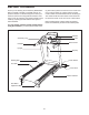
BEFORE YOU BEGIN Thank you for selecting the revolutionary PROFORM® 695 LT treadmill. The 695 LT treadmill offers an impressive selection of features designed to make your workouts at home more enjoyable and effective. And when youʼre not exercising, the unique treadmill can be folded up, requiring less than half the floor space of other treadmills. ing this manual, please see the front cover of this manual.
ASSEMBLY Assembly requires two persons. Set the treadmill in a cleared area and remove all packing materials. Do not dispose of the packing materials until assembly is completed. Note: The underside of the treadmill walking belt is coated with high-performance lubricant. During shipping, some lubricant may be transferred to the top of the walking belt or the shipping carton. This is normal and does not affect treadmill performance.
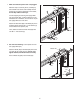
1. Make sure that the power cord is unplugged. 1 With the help of a second person, carefully tip the treadmill onto its left side. Partially fold the Frame (55) so that the treadmill is more stable; do not fully fold the Frame yet. Hole 87 90 5 Cut the shipping tie securing the Upright Wire (87) to the Base (95). Locate a plastic tie in the indicated hole in the Base, and use the tie to pull the Upright Wire out of the hole.
3. Identify the Right Upright (85) and the Right Upright Spacer (91), which are marked with “Right” stickers. 3 Insert the Upright Wire (87) through the Right Upright Spacer (91) as shown. Set the Right Upright Spacer on the Base (95). See inset drawings B and C. Make sure that the Right Upright Spacer sits flush against the Base. If necessary, turn the Right Upright Spacer and try again. 87 85 Wire Tie 87 91 95 A Have a second person hold the Right Upright (85) near the Base (95).
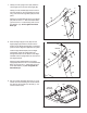
5. With the help of a second person, carefully tip the treadmill onto its right side. Partially fold the Frame (55) so that the treadmill is more stable; do not fully fold the Frame yet. 5 89 Attach a Wheel (96) to the Base (95) with a 3/8" x 2" Bolt (8) and a 3/8" Nut (10). Do not overtighten the Nut; the Wheel must turn freely. 8 Press a Base Cap (89) into the Base (95). 95 6. Hold a Bolt Spacer (14) inside the lower end of the Left Upright (84).
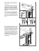
7. Identify the Left Upright Cover (80). Slide the Left Upright Cover onto the Left Upright (84). Identify the Left Handrail (82). Remove the tie from the bracket on the Left Handrail. If necessary, press the 5/16" Cage Nuts (38) back into place. 7 4 38 Tie 13 82 Attach the Left Handrail (82) to the Left Upright (84) with two 5/16" x 1" Flat Head Patch Bolts (3) and a 5/16" x 1" Patch Bolt (4) with a 5/16" Star Washer (13). Do not tighten the Patch Bolts yet. 3 84 80 8.
10. IMPORTANT: To avoid damaging the Crossbar (107), do not use power tools and do not overtighten the #10 x 3/4" Screws (2). 10 First 2 12 Orient the Crossbar (107) as shown. Attach the Crossbar to the Handrails (82, 83) with four #10 x 3/4" Screws (2) and four #10 Star Washers (12); do not tighten the Screws yet. 82 Insert the Console Frame (102) into the Handrails (82, 83). Attach the Console Frame with four 1/4" x 1" Patch Bolts (9); do not tighten the Patch Bolts yet.
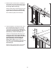
. Set the console assembly on the Handrails (82, 83). Be careful not to pinch any wires. Insert the excess Upright Wire (87) into the Right Handrail. 12 Attach the console assembly to the Crossbar (107) with six #8 x 3/4" Screws (1). Start all six Screws, and then tighten all of them. Console Assembly 87 105 Attach the two Console Clamps (105) to the console assembly with four #8 x 1" Screws (53). 53 83 13. Hold the Right Upright Cover (86) against the console assembly.
14. If necessary, press the Left Tray (103) and the Right Tray (104) into the console assembly. 14 Console Assembly 103 104 15. Raise the Frame (55) to the position shown. Have a second person hold the Frame until this step is completed. 15 Orient the Storage Latch (51) so that the large barrel and the latch knob are oriented as shown. 55 10 Attach the upper end of the Storage Latch (51) to the bracket on the Frame (55) with a 3/8" x 2" Bolt (8) and a 3/8" Nut (10).
OPERATION AND ADJUSTMENT THE PRE-LUBRICATED WALKING BELT Your treadmill features a walking belt coated with highperformance lubricant. IMPORTANT: Never apply silicone spray or other substances to the walking belt or the walking platform. Such substances will cause excessive wear. HOW TO PLUG IN THE POWER CORD DANGER: Improper connection that is properly installed and grounded in accordance with all local codes and ordinances. IMPORTANT: The treadmill is not compatible with GFCI-equipped outlets.
CONSOLE DIAGRAM FEATURES OF THE CONSOLE The treadmill console offers an impressive array of features designed to make your workouts more effective and enjoyable. When the manual mode of the console is selected, you can change the speed and incline of the treadmill with the touch of a button. As you exercise, the console will display instant exercise feedback. You can even measure your heart rate using the handgrip pulse sensor. In addition, the console offers sixteen quick calorie burn workouts.
HOW TO TURN ON THE POWER HOW TO USE THE MANUAL MODE IMPORTANT: If the treadmill has been exposed to cold temperatures, allow it to warm to room temperature before turning on the power. If you do not do this, you may damage the console displays or other electrical components. Plug in the power cord (see page 14). Next, locate the power switch on the treadmill frame near the power cord. Make sure that the switch is in the reset position. 1. Insert the key into the console.
4. Change the incline of the treadmill as desired. To reset the displays, press the Stop button, remove the key, and then reinsert the key. To change the incline of the treadmill, press the Incline increase and decrease buttons or one of the numbered incline buttons. Each time you press one of the incline buttons, the treadmill will gradually adjust to the selected incline setting. 6. Measure your heart rate if desired.
HOW TO USE A PRESET WORKOUT Note: The calorie goal is an estimate of the number of calories that you will burn during the workout. The actual number of calories that you burn will depend on your weight. In addition, if you manually change the speed or incline of the treadmill during the workout, the number of calories you burn will be affected. 1. Insert the key into the console. See HOW TO TURN ON THE POWER on page 16. 2. Select a preset workout.
HOW TO USE AN IFIT WORKOUT To purchase iFit cards at any time, go to www.iFit.com or call the telephone number on the front cover of this manual. iFit cards are also available at select stores. 3. Start the walking belt. Press the Go button or the Speed increase button to start the workout. A moment after you press the button, the treadmill will automatically adjust to the first speed and incline settings of the workout. Hold the handrails and begin walking. 1. Insert the key into the console.
THE INFORMATION MODE The console features an information mode that keeps track of the total number of hours that the treadmill has been used and the total distance that the walking belt has moved. The information mode also allows you to select miles or kilometers as the unit of measurement and to turn on and turn off the display demo mode. To select the information mode, hold down the Stop button while inserting the key into the console and then release the Stop button.
HOW TO FOLD AND MOVE THE TREADMILL HOW TO FOLD THE TREADMILL HOW TO MOVE THE TREADMILL To avoid damaging the treadmill, adjust the incline to the lowest position before you fold the treadmill. Then, remove the key and unplug the power cord. CAUTION: You must be able to safely lift 45 lbs. (20 kg) to raise, lower, or move the treadmill. Before moving the treadmill, fold it as described at the left. CAUTION: Make sure that the latch knob is locked in the storage position.
TROUBLESHOOTING Most treadmill problems can be solved by following the simple steps below. Find the symptom that applies, and follow the steps listed. If further assistance is needed, see the front cover of this manual. PROBLEM: The power does not turn on SOLUTION: a. Make sure that the power cord is plugged into a surge suppressor, and that the surge suppressor is plugged into a properly grounded outlet (see page 14).
Remove the three #8 x 3/4" Screws (1) and carefully pivot the Motor Hood (62) off. 62 Locate the Reed Switch (73) and the Magnet (47) on the left side of the Pulley (48). Turn the Pulley until the Magnet is aligned with the Reed Switch. Make sure that the gap between the Magnet and the Reed Switch is about 1/8 in. (3 mm). If necessary, loosen the #8 x 3/4" Truss Head Screw (18), move the Reed Switch slightly, and then retighten the Screw. Reattach the Motor Hood (not shown).
PROBLEM: The walking belt is off-center or slips when walked on SOLUTION: a. If the walking belt is off-center, first remove the key and UNPLUG THE POWER CORD. If the walking belt has shifted to the left, use the hex key to turn the left idler roller bolt clockwise 1/2 of a turn; if the walking belt has shifted to the right, turn the left idler roller bolt counterclockwise 1/2 of a turn. Be careful not to overtighten the walking belt.
EXERCISE GUIDELINES WARNING: Before beginning this Burning Fat—To burn fat effectively, you must exercise at a low intensity level for a sustained period of time. During the first few minutes of exercise, your body uses carbohydrate calories for energy. Only after the first few minutes of exercise does your body begin to use stored fat calories for energy. If your goal is to burn fat, adjust the intensity of your exercise until your heart rate is near the lowest number in your training zone.
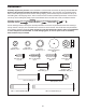
PART LIST—Model No. PCTL69010.0 To locate the parts listed below, see the EXPLODED DRAWING near the end of this manual. Key No. Qty. 1 2 3 4 5 6 7 8 9 10 11 12 13 14 15 16 17 18 19 20 21 22 23 24 25 26 27 28 29 30 31 32 33 34 35 36 37 38 39 40 41 42 43 44 45 46 47 48 49 50 25 4 4 2 4 1 4 3 4 3 4 4 2 4 5 3 3 11 2 2 2 2 1 2 1 1 2 7 1 8 2 4 2 2 4 4 3 2 2 1 1 2 2 1 2 2 1 1 1 1 Description Key No. Qty.
Key No. Qty. 101 102 103 104 105 106 107 1 1 1 1 2 1 1 Description Key No. Qty. Console Console Frame Left Tray Right Tray Console Clamp Console Base Crossbar 108 109 * * * * * 1 1 – – – – – Description Access Door Console Ground Wire 8" Blue Wire, M/F 10" Blue Wire, 2F 12" Red Wire, M/F 10" Black Wire, M/F Userʼs Manual Note: Specifications are subject to change without notice. For information about ordering replacement parts, see the back cover of this manual. *These parts are not illustrated.
24 34 33 19 56 30 28 61 18 59 36 60 21 41 30 24 42 40 34 33 19 28 18 18 39 36 18 58 57 21 32 43 18 30 56 20 30 55 44 36 30 52 10 54 45 46 30 49 18 48 47 8 42 18 18 51 32 20 39 30 43 36 23 30 45 46 6 EXPLODED DRAWING A—Model No. PCTL69010.
EXPLODED DRAWING B—Model No. PCTL69010.
EXPLODED DRAWING C—Model No. PCTL69010.
EXPLODED DRAWING D—Model No. PCTL69010.
ORDERING REPLACEMENT PARTS To order replacement parts, please see the front cover of this manual.