Model No. PFEVEX71708.0 Serial No. Write the serial number in the space above for reference. Serial Number Decal QUESTIONS? As a manufacturer, we are committed to providing complete customer satisfaction. If you have questions, or if there are missing parts, please contact us at the numbers or addresses listed below: Call: 08457 089 009 Outside UK: 0 (44) 113 3877133 Fax: 0 (44) 113 3877125 E-mail: csuk@iconeurope.com Write: ICON Health & Fitness, Ltd.
TABLE OF CONTENTS WARNING DECAL PLACEMENT . . . . . . . . . . . . . . . . . . . . . . . . . . . . . . . . . . . . . . . . . . . . . . . . . . . . . . . . . . . . . .2 IMPORTANT PRECAUTIONS . . . . . . . . . . . . . . . . . . . . . . . . . . . . . . . . . . . . . . . . . . . . . . . . . . . . . . . . . . . . . . . .3 BEFORE YOU BEGIN . . . . . . . . . . . . . . . . . . . . . . . . . . . . . . . . . . . . . . . . . . . . . . . . . . . . . . . . . . . . . . . . . . . . . .4 ASSEMBLY . . . . . . . . . . . . .
IMPORTANT PRECAUTIONS WARNING: To reduce the risk of serious injury, read all important precautions and instructions in this manual and all warnings on your exercise cycle before using your exercise cycle. ICON assumes no responsibility for personal injury or property damage sustained by or through the use of this product. 8. Wear appropriate exercise clothes while exercising; do not wear loose clothes that could become caught on the exercise cycle.
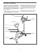
BEFORE YOU BEGIN Congratulations for selecting the new PROFORM® 700 exercise cycle. Cycling is one of the most effective exercises for increasing cardiovascular fitness, building endurance, and toning the body. The 700 exercise cycle offers a selection of features designed to let you enjoy this healthful exercise in the convenience and privacy of your home. after reading this manual, please see the front cover of this manual.
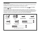
ASSEMBLY Assembly requires two persons. Place all parts of the exercise cycle in a cleared area and remove the packing materials. Do not dispose of the packing materials until assembly is completed. In addition to the included tools, assembly requires an adjustable wrench screwdriver . and a Phillips Use the part drawings below to identify the small parts used in assembly. The number in parentheses below each drawing refers to the key number of the part, from the PART LIST near the end of this manual.
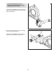
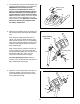
1. 1 To make assembly easier, read the information on page 5 before you begin assembling the exercise cycle. Insert the Rear Stabilizer (6) into the Frame (1). Attach the Rear Stabilizer with four M8 x 60mm Button Screws (30). 1 6 30 2. Orient the Front Stabilizer (2) so that the large holes are facing the Frame (1). 2 Attach the Front Stabilizer (2) to the Frame (1) with two M8 x 73mm Button Screws (33).
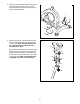
3. Attach the Left and Right Frame Covers (19, 3) around the Frame (1) with an M4 x 15mm Round Head Screw (58) and two M5 x 15mm Round Head Screws (59). 3 3 58 1 19 59 4. Attach the Seat (12) to the Seat Carriage (29) with four M8 Split Washers (42) and four M8 Locknuts (10). Note: The Split Washers and the Locknuts may be preattached to the underside of the Seat. 4 12 Set the Seat Carriage (29) in the bracket on the Seat Post (5).
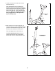
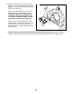
5. Loosen and remove the Seat Post Knob (9) from the Frame (1). 5 Insert the Seat Post (5) into the Frame (1). Adjust the Seat Post to the desired height and insert the Seat Post Knob through the indicated hole in the Frame into one of the adjustment holes in the Seat Post. Then, tighten the Seat Post Knob. Make sure the Seat Post Knob is firmly engaged in one of the adjustment holes in the Seat Post. 5 1 6.
7. The Console (16) can use four AA batteries (not included); alkaline batteries are recommended. IMPORTANT: If the Console has been exposed to cold temperatures, allow it to warm to room temperature before inserting batteries. Otherwise, you may damage the console displays or other electronic components. Remove the battery cover, insert the batteries into the battery compartment, and reattach the battery cover. Make sure to orient the batteries as shown by the diagram inside the battery compartment.
. Identify the Left Pedal (24), which is marked with an “L.” Using an adjustable wrench, firmly tighten the Left Pedal counterclockwise into the left arm of the Crank (21). 10 Tighten the Right Pedal (not shown) clockwise into the right arm of the Crank (not shown). IMPORTANT: Tighten both pedals as firmly as possible. After using the exercise cycle for one week, retighten the pedals. For best performance, keep the pedals tightened.
HOW TO USE THE EXERCISE CYCLE HOW TO ADJUST THE SEAT POST HOW TO ADJUST THE SEAT For effective exercise, the seat should be at the proper height. As you Seat pedal, there should be a slight bend in your knees when the pedals are in the Seat Post lowest position. To adjust the height of Hole the seat, first loosen and remove the seat Seat Post Knob post knob. Next, slide the seat post upward or downward and align one of the adjustment holes in the seat post with the indicated hole in the frame.
CONSOLE DIAGRAM 2. Select the manual mode. When you turn on the console, the manual mode will be selected. If you have selected a program, reselect the manual mode by pressing the Smart Programs button repeatedly until zeros appear in the display. 3. Change the resistance of the pedals as desired. As you pedal, change the resistance of the pedals by pressing the Resistance increase and decrease buttons. There are ten resistance levels.
When you turn the power on, the scan display will be selected automatically. An indicator will appear below the word SCAN to show that the scan display is selected. Note: The console can display speed and distance in either miles or kilometers. The letters MPH or Km/H will appear in the display to show which unit of measurement is selected. To change the unit of measurement, hold down the On/Reset button for several seconds until the desired unit of measurement appears in the display.
HOW TO USE A SMART PROGRAM As the target Target Pace Meter pace meter changes in height during the program, adjust your pedaling pace so that the same number of bars appears in both Pace Meter meters. If your pedaling pace is slower than the current target pace setting, an arrow will appear next to the pace meter to prompt you to increase your pace; if your pace is faster than the target pace, an arrow will prompt you to decrease your pace. 1. Turn on the console.
MAINTENANCE AND TROUBLESHOOTING When the reed switch is correctly adjusted, reattach the left shield, the frame covers, the upright covers, and the left pedal. Inspect and tighten all parts of the exercise cycle regularly. Replace any worn parts immediately. To clean the exercise cycle, use a damp cloth and a small amount of mild detergent. IMPORTANT: To avoid damage to the console, keep liquids away from the console and keep the console out of direct sunlight.
EXERCISE GUIDELINES WARNING: Burning Fat—To burn fat effectively, you must exercise at a low intensity level for a sustained period of time. During the first few minutes of exercise, your body uses carbohydrate calories for energy. Only after the first few minutes of exercise does your body begin to use stored fat calories for energy. If your goal is to burn fat, adjust the intensity of your exercise until your heart rate is near the lowest number in your training zone.
SUGGESTED STRETCHES 1 The correct form for several basic stretches is shown at the right. Move slowly as you stretch—never bounce. 1. Toe Touch Stretch Stand with your knees bent slightly and slowly bend forward from your hips. Allow your back and shoulders to relax as you reach down toward your toes as far as possible. Hold for 15 counts, then relax. Repeat 3 times. Stretches: Hamstrings, back of knees and back. 2 2. Hamstring Stretch Sit with one leg extended.
PART LIST—Model No. PFEVEX71708.0 Key No. Qty. 1 2 3 4 5 6 7 8 9 10 11 12 13 14 15 16 17 18 19 20 21 22 23 24 25 26 27 28 29 30 31 32 33 1 1 1 2 1 1 2 2 1 4 1 1 1 1 1 1 1 1 1 1 1 1 1 1 1 1 2 2 1 4 2 2 2 Description Key No. Qty.
EXPLODED DRAWING—Model No. PFEVEX71708.
ORDERING REPLACEMENT PARTS To order replacement parts, please see the front cover of this manual. To help us assist you, be prepared to provide the following information when contacting us: • the model number and serial number of the product (see the front cover of this manual) • the name of the product (see the front cover of this manual) • the key number and description of the replacement part(s) (see the PART LIST and the EXPLODED DRAWING near the end of this manual) Part No.