
Owner's Manual

5
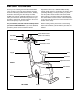
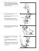
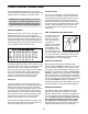
5. Attach the Handlebar (4) to the Upright (2) with
two M10 x 25mm Botton Head Screws (25) and
two M10 Split Washers (26).
6. Attach the Seat (16) to the Seat Post (3) with
four M8 Split Washers (41) and four M8 Nylon
Locknuts (20).
Insert the Seat Post (3) into the Frame (1).
Press the Frame Bushing (17) into place in the
Frame.
Align one of the holes in the Seat Post (3) with
the hole in the Frame (1). Insert the Lock Knob
(14) into the Frame and the Seat Post. Tighten
the Lock Knob.
5
26
1
17
20
41
3
16
41
20
14
25
4
2
9
8
2
10
22
22
13
Console Wire
4
3
25
25
26
2
1
26
26
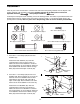
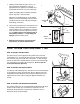
3. Attach the Upright (2) to the Frame (1) with
three M10 x 25mm Button Head Screws (25)
and three M10 Split Washers (26).
Be careful
not to pinch the Reed Switch Wire (13) or the
Resistance Cable (10).
13
10
6
4. Connect the Reed Switch Wire (13) to the wire
on the back of the Console (8).
Attach the Console (8) to the Upright (2) with four
M4 x16mm Screws (22).
Press the Resistance Knob (9) onto the
Resistance Control (10). Be sure that the mark
on the Resistsance Knob ais correctly aligned.