
User`s manual


8
50
8
38
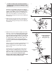
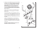
7. Identify the Left Handlebar (6), which is marked with a
“Left” sticker. Insert the Left Handlebar into one of the
H
andlebar Legs (5); m
ake sure that the Handlebar
Leg is turned so the hexagonal holes are on the
i
ndicated side
.
Attach the Left Handlebar with two
M8 x 45mm Button Bolts (50) and two M8 Nylon
Locknuts (38).
Make sure that the Nylon Locknuts
are inside the hexagonal holes. Do not tighten the
Button Bolts yet.
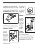
Apply a generous amount of the included grease to
the Pivot Axle (7). Then apply grease to two Wave
Washers (43).
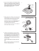
Insert the Pivot Axle (7) into the Upright (2), and cen-
ter the Pivot Axle. Turn a Handlebar Spacer (47) so that
the small arrow on the Handlebar Spacer points toward
the floor, and slide the Handlebar Spacer onto the Left
Handlebar (6). Next, slide a Wave Washer (43) onto the
Pivot Axle.
Slide the Left Handlebar (6) onto the Pivot Axle (7).
Attach the Left Handlebar with an M8 x 25mm Patch
Screw (56) and a Handlebar Washer (55). Then, press
the tabs on a Handlebar Cap (46) into the Handlebar
Spacer (47).
Assemble the Right Handlebar (8) and the other
Handlebar Leg (5) in the same way.
5
2
5
Hexagonal
Holes
7
Grease
46
Tabs
Arrow
6
55
43
56
47
7