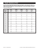
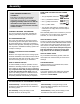
Weight Resistance Chart This chart shows the approximate weight resistance at each station. ÒTopÓ refers to the 10 lbs. top weight. The other numbers refer to the 10 lbs. weight plates. Note: The actual resistance at each weight station may vary due to differences in individual weight plates, as well as friction between the cables, pulleys, and weight guides. Arm Press Lower Pulley Upper Pulley Ab Pulley Leg Lever (lbs.) (lbs.) (lbs.) (lbs.) (lbs.
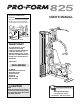
Model No. PFEMSY75000 Serial No. USERÕS MANUAL The serial number is found in the location shown below. Write the serial number in the space above. Serial Number Decal QUESTIONS? As a manufacturer, we are committed to providing complete customer satisfaction. If you have questions, or if there are missing parts, we will guarantee complete satisfaction through our Customer Service Department. Please CALL: 0345-089009 Or WRITE: ICON Fitness Lifestyle Ltd.
Table of Contents How To Order Replacement Parts . . . . . . . . . . . . . . . . . . . . . . . . . . . . . . . . . . . . . . . . . . . . . . . . . . . . . . . . . . 2 Important Precautions . . . . . . . . . . . . . . . . . . . . . . . . . . . . . . . . . . . . . . . . . . . . . . . . . . . . . . . . . . . . . . . . . . . 3 Before You Begin . . . . . . . . . . . . . . . . . . . . . . . . . . . . . . . . . . . . . . . . . . . . . . . . . . . . . . . . . . . . . . . . . . . . . . 4 Assembly . . . . . . . . . .
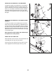
Trouble-shooting and Maintenance Inspect and tighten all parts each time you use the training system. Replace any worn parts immediately. The training system can be cleaned using a damp cloth and mild non-abrasive detergent. Do not use solvents. TIGHTENING THE CABLES 73 Woven cable, the type of cable used on the training system, can stretch slightly when it is first used. If there is slack in the Cables before resistance is felt, the Cables should be tightened.
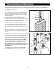
ADJUSTING THE POSITION OF THE BACKREST To adjust the position of the Backrest (41), unscrew the handle of the Adjustment Knob (9) until it is loose. Pull out the handle as far as it will go and slide the Backrest Frame (15, not visible) to the desired position. Release the handle until the Knob snaps into one of the adjustment holes on the Backrest Frame. Then tighten the handle again.
Important Precautions WARNING: To reduce the risk of serious injury, read the following important precautions before using the training system. 8. Keep children under the age of 12 and pets away from the training system at all times. 1. It is the responsibility of the owner to ensure that all users of the training system are adequately informed of all precautions. 9. Keep hands and feet away from moving parts. 2.
Before You Begin Thank you for selecting the versatile PROFORM¨ 825 training system. The PROFORM¨ 825 offers a selection of weight stations designed to develop every major muscle group of the body. Whether your goal is to tone your body, build dramatic muscle size and strength, or improve your cardiovascular system, the PROFORM¨ 825 will help you to achieve the results you want. have additional questions, please call our our Customer Service Department at 0345-089009.
Adjustment The instructions below describe how each part of the training system can be adjusted. IMPORTANT: When attaching the lat bar, row bar, ankle strap or ab strap, make sure that the attachments are in the correct starting position for the exercise to be performed. If there is any slack in the cables or chain as an exercise is performed, the effectiveness of the exercise will be reduced.
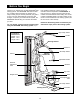
Cable Diagram The cable diagram below shows the proper routing of the High Cable (73) and the Low Cable (72). The numbers show the correct route for each Cable. Make sure that the Cables are routed correctly, that the pulleys move smoothly and that the cable traps do not touch or bind the Cables. Incorrect cable routing can damage the training system.
Assembly MAKE SURE YOU HAVE THE FOLLOWING TOOLS: MAKE ASSEMBLY EASIER FOR YOURSELF! ¥ Two (2) adjustable wrenches Everything in this manual is designed to ensure that the training system can be assembled successfully by anyone.
1 Frame Assembly 33 1. Before beginning assembly, make sure you have read and understood the information on page 5. 24 Locate and open the parts bag labelled ÒFRAME ASSEMBLY.Ó 12 Support Tube 33 Press a 2Ó Square Inner Cap (33) into each open tube on the Press Frame (12). 3 Press a 2Ó Square Inner Cap (33) into the support tube on the Main Upright (3). Press a 2Ó x 3Ó Inner Cap (24) into the open end of the Main Upright (3).
26 Miscellaneous Assembly 26. Note: Some of the parts used in miscellaneous assembly are located in the parts bag labelled ÒSeat Assembly.Ó 38 Slide the four Threaded Clips (38) down over the slots in the bracket on the Stabiliser (5). 5 38 27. Attach the upper end of the Shroud (56) to the two ÒLÓ-brackets on the Top Frame (1) with two 1/4Ó x 3/4Ó Bolts (17), two 1/4Ó Flat Washers (71) and two 1/4Ó Nylon Locknuts (25).
23. Press a 1Ó x 2Ó Inner Cap (43) into each end of the Backrest Frame (15). 23 43 41 17 Attach the Backrest (41) to the Backrest Frame (15) with four 1/4Ó x 3/4Ó Bolts (17). 34 Press a 3/4Ó Round Inner Cap (34) into each end of the pad tube on the Backrest Frame (15). 15 Slide a Leg Foam Roller (74) onto each end of the pad tube on the Backrest Frame (15). Note: The Leg Foam Rollers are thinner than the four Foam Rollers (30) used in step 25. 17 74 74 43 Pad Tube 34 24.
3. Attach the Leg Lever Lock (11) to the front leg with a 5/16Ó x 3Ó Bolt (78), three 5/16Ó Flat Washers (80) and a 5/16Ó Nylon Jamnut (79). Do not overtighten the Nylon Jamnut; it must be easy to turn the Leg Lever Lock. 3 80 78 Front Leg Attach the Leg Lever Bumper (6) to the front leg with a #10 x 1Ó Tap Screw (7). 11 6 7 80 79 4. Attach the Foot Plate (4) to the Base (8) with a 3/8Ó x 5 1/2Ó Bolt (57) and a 3/8Ó Nylon Locknut (50). 4 57 8 4 50 5.
6. See the inset drawing. Press two Weight Inserts (77) into the indicated holes in each Weight (26). Make sure the large pin groove is oriented as shown. Slide all of the included Weights (26) onto the two Weight Guides (23). Make sure the Weights are oriented correctly. The holes must be turned towards the front of the unit, as shown. Slide the Top Weight (16) with the pre-attached Weight Tube (36) onto the Weight Guides (23). The Weight Tube slides into the hole in the centre of the Weights (26).
20 Arm Assembly 12 50 20. Note: Some of the parts used in arm assembly are located in the parts bag labelled ÒSeat Assembly.Ó 46 50 Attach the Press Arm (46) to the Press Frame (12) with two 3/8Ó x 3Ó Bolts (45) and two 3/8Ó Nylon Locknuts (50). 45 21. Press a 2Ó Square Inner Cap (33) into each end of the Press Arm (46). Insert a Handle (20) into the indicated hole on one side of the Press Arm (46) from the direction shown.
. Slide a Cable Trap (44) onto a 3/8Ó x 4Ó Bolt (65). 17 44 72 Wrap the Low Cable (72) around a 4Ó Pulley (35). Attach the Pulley to the indicated hole in the Main Upright (3) with the 3/8Ó Bolt (65), the Cable Trap (44), a Pulley Bushing (42), a 3/8Ó Flat Washer (55), and a 3/8Ó Nylon Jamnut (63). Make sure the Cable Trap is oriented as shown, so it will hold the Cable in place. 65 42 3 55 35 63 18. Feed the end of the Low Cable (72) through the indicated slot in the Main Upright (3).
8. Remove the upper of the two 3/8Ó x 3Ó Bolts (45) attaching the Top Frame (1) to the Main Upright (3). 8 35 45 55 54 Slot Feed the bolt on the High Cable (73) through the indicated slot in the Main Upright (3) in the direction shown. 50 42 73 1 Note: Follow the procedure described in step 7 for attaching all Pulleys. Wrap the High Cable (73) around a 4Ó Pulley (35) in the direction shown.
11. Wrap the High Cable (73) around a 4Ó Pulley (35). Attach the Pulley to the Main Upright (3) with a 3/8Ó x 2 1/2Ó Bolt (54), two 3/8Ó Flat Washers (55), two Pulley Bushings (42) and a 3/8Ó Nylon Jamnut (63). 11 42 55 54 35 73 63 42 55 3 12. Dis-assemble the pre-assembled Pulley Plates (31). Note that on one end, the Pulley Plates have several adjustment holes. These holes must be closest to the floor. Wrap the High Cable (73) around a 4Ó Pulley (35).
14. The Low Cable (72) is the only remaining Cable. It is approximately 206Ó long. Note that it has a large ball on one end and a small ball on the other. 14 Route the smaller ball on the Low Cable (72) through the indicated slots in the Leg Lever (29) and the front leg on the Base (8). Attach a 4Ó Pulley (35) inside the slot in the Leg Lever (29) with a 3/8Ó x 2 1/2Ó Bolt (54), two 3/8Ó Flat Washers (55), two Pulley Bushings (42) and a 3/8Ó Nylon Jamnut (63).
3/4" Round Inner Cap (34) 1" x 2Ó Inner Cap (43) 2" x 3Ó Inner Cap (24) 2" Square Inner Cap (33)
REMOVE THIS PART IDENTIFICATION CHART FROM THE MANUAL This chart is provided to help you identify the small parts used in assembly. The number in parenthesis below each part refers to the key number of the part. Important: Some parts may have been pre-assembled for shipping purposes. If you cannot find a part in the parts bags, check to see if it has been pre-assembled.
Part Identification ChartÑPFEMSY75000 1/4" Nylon Jamnut (51 ) R1100A 1/4" Flat Washer (71) 1/4" Nylon Locknut (25) 5/16" Nylon Locknut (21) 1/4" x 1 1/2" Screw (49) 5/16" Nylon Jam Nut (93) 1/4" x 3/4" Bolt (17) 5/16" Flat Washer (8) 5/16" x 3" Bolt (78) 1/2" x 3 1/2" Bolt (22) 1/2" Plain Nut (68) Cable Clip (69) 1/2" Nylon Jamnut (48) #8 x 3/4" Screw (32) #10 x 1" Tap Screw (7) 1 1/2" Flat Washer (40)
3/8" Nylon Jam Nut (63) 3/8" x 1 3/4" Bolt (60) 3/8" x 2" Bolt (62) 3/8" x 2 1/2" Bolt (54) 3/8" x 3" Bolt (45) 3/8" x 4" Bolt (65) 3/8" x 3 3/4" Carriage Bolt (52) 3/8" x 5 1/2" Bolt (57) 3/8" Flat Washer (55) Pulley Bushing (42) 3/8" x 8" Bolt (59) 3/8" Nylon Locknut (50)
Part ListÑModel No. PFEMSY75000 Key No. Qty.
81 REMOVE THIS PART LIST/EXPLODED DRAWING FROM THE MANUAL
Exploded DrawingÑModel No.
33 33 58 58 35 18 42 18 70 61 27 58 53 18 54 73 63 59 63 53 55 14 43 58 17 55 14 35 50 24 74 42 34 35 12 15 50 17 33 45 74 43 41 34 9 46 58 65 35 20 13 30 44 34 17 42 17 20 9 37 33 28 9 33 47 33 78 47 78 80 80 34 48 54 6 29 7 55 80 55 54 55 42 63 34 42 50 28 30 57 79 30 11 65 8 22 4 35 63 55 35 42 33 42 72 33