Model No. 831.23743.0 Serial No. Write the serial number in the space above for reference. ELLIPTICAL EXERCISER User’s Manual Serial Number Decal • Assembly • Operation • Maintenance • Part List and Drawing CAUTION Read all precautions and instructions in this manual before using this equipment. Keep this manual for future reference. Sears, Roebuck and Co.
TABLE OF CONTENTS WARNING DECAL PLACEMENT . . . . . . . . . . . . . . . . . . . . . . . . . . . . . . . . . . . . . . . . . . . . . . . . . . . . . . . . . . . . . .2 IMPORTANT PRECAUTIONS . . . . . . . . . . . . . . . . . . . . . . . . . . . . . . . . . . . . . . . . . . . . . . . . . . . . . . . . . . . . . . . .3 BEFORE YOU BEGIN . . . . . . . . . . . . . . . . . . . . . . . . . . . . . . . . . . . . . . . . . . . . . . . . . . . . . . . . . . . . . . . . . . . . . .4 ASSEMBLY . . . . . . . . . . . . . .
IMPORTANT PRECAUTIONS WARNING: To reduce the risk of serious injury, read all important precautions and instructions in this manual and all warnings on your elliptical exerciser before using your elliptical exerciser. Sears assumes no responsibility for personal injury or property damage sustained by or through the use of this product. 1. Before beginning any exercise program, consult your physician. This is especially important for persons over the age of 35 or persons with pre-existing health problems.
BEFORE YOU BEGIN Thank you for purchasing the revolutionary PROFORM® XP 420 Razor elliptical exerciser. The XP 420 Razor elliptical exerciser provides a wide array of features designed to make your workouts at home more effective and enjoyable. cover of this manual. To help us assist you, note the product model number and serial number before contacting us. The model number and the location of the serial number decal are shown on the front cover of this manual.
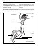
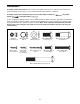
ASSEMBLY Assembly requires two persons. Place all parts of the elliptical exerciser in a cleared area and remove the packing materials. Do not dispose of the packing materials until assembly is completed. Assembly requires the included hex keys and your own Phillips screwdriver wrench , and rubber mallet . , adjustable As you assemble the elliptical exerciser, use the drawings below to identify small parts.
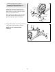
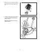
1. 1 To make assembly easier, read the information on page 5 before you begin assembling the elliptical exerciser. Identify the Left Frame Cover (48), which is marked with an “L” sticker. Orient the Left and Right Frame Covers (48, 49) with the rounded sides in the indicated locations. 48 While another person lifts the rear of the Frame (1), attach each Frame Cover (48, 49) to the Frame with two M4 x 16mm Screws (84). Rounded Side Rounded Side 84 1 49 84 2.
3. Tip: Be careful not to pinch the Wire Harness (100) during this step. Start all screws before tightening any of them. 3 Wire Tie Have another person hold the Upright (2) near the Frame (1). Locate the wire tie in the Upright. Tie the lower end of the wire tie to the Wire Harness (100). Next, pull the upper end of the wire tie upward out of the top of the Upright. Then, untie and discard the wire tie.
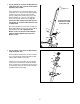
5. The Console (4) can be operated with four 1.5V “D” batteries (not included); alkaline batteries are recommended. IMPORTANT: If the elliptical exerciser has been exposed to cold temperatures, allow it to warm to room temperature before inserting batteries into the Console. If you do not do this, the console displays or other electronic components may become damaged. Remove the two screws from the back of the console, and remove the battery cover. Insert four batteries into the Console.
7. Slide the Console Cover (96) (see the drawing in step 6) upward to the Console (4). Attach the Console Cover with two M4 x 16mm Screws (84). 7 4 96 84 8. Attach the Left Pedal (12) to the left Pedal Arm (14) with three M10 x 70mm Button Screws (75), three Split Washers (78), and an M4 x 16mm Screw (84). 8 14 Repeat this step on the right side of the elliptical exerciser.
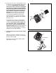
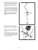
9. Identify the Left Upper Body Arm (8), which is marked with an “L” sticker. Orient the Left Upper Body Arm and the left Upper Body Leg (6) as shown; make sure that the hexagonal holes in the Left Upper Body Arm are in the indicated location. 9 8 Slide the Left Upper Body Arm (8) onto the left Upper Body Leg (6). Attach the Left Upper Body Arm with two M6 x 38mm Button Bolts (76) and two M6 Nylon Locknuts (77); make sure that the Nylon Locknuts are inside the hexagonal holes.
. Apply a small amount of grease to a Pedal Arm Axle (21). While another person holds the right Pedal Arm (14) inside the bracket on the right Upper Body Leg (6), insert the Pedal Arm Axle through the Upper Body Leg and the Pedal Arm. 11 6 14 6 80 Grease 21 22 Then, tighten an M6 x 16mm Button Screw (80) and an Axle Cover (22) into each end of the Pedal Arm Axle (21). 22 80 14 Repeat this step for the other side of the elliptical exerciser. 12.
HOW TO USE THE ELLIPTICAL EXERCISER HOW TO MOVE THE ELLIPTICAL EXERCISER HOW TO EXERCISE ON THE ELLIPTICAL EXERCISER To move the elliptical exerciser, stand in front of it, place one foot against one of the wheels, and firmly hold the upper end of the upright. Pull the upright forward until you can move the elliptical exerciser on the wheels. Carefully move the elliptical exerciser to the desired location and then lower it to the floor.
HOW TO ADJUST THE STRIDE OF THE ELLIPTICAL EXERCISER Crank Arm To adjust the stride of the elliptical exerciser, first pull one of the adjustment knobs until the adjustment bracket pivots freely. Pivot the adjustment bracket until the adjustment knob is aligned with one of the holes in the crank arm, and gently release the knob. Then, pivot the adjustment bracket back and forth slightly to make sure that the adjustment pin is engaged in one of the holes in the crank arm.
CONSOLE DIAGRAM The console also offers four preset workouts. Each preset workout automatically changes the resistance of the pedals and prompts you to increase or decrease your pedaling pace as it guides you through an effective workout. FEATURES OF THE CONSOLE The advanced console offers an array of features designed to make your workouts more effective and enjoyable. When you use the manual mode of the console, you can change the resistance of the pedals with the touch of a button.
HOW TO USE THE MANUAL MODE The lower left display–This display can show the elapsed time and the approximate number of calories you have burned. Note: During a workout, the display will show the time remaining in the workout. Note: If there is a sheet of clear plastic on the face of the console, remove the plastic. 1. Press the Display button or the decrease button on the console, or begin pedaling to turn on the console.
5. Measure your heart rate if desired. If your heart rate is not shown, make sure that your hands are positioned as described. Be careful not to move your hands excessively or to squeeze the metal contacts tightly. For optimal performance, clean the metal contacts using a soft cloth; never use alcohol, abrasives, or chemicals to clean the contacts. If there are sheets of clear Contacts plastic on the metal contacts on the handgrip pulse sensor, remove the plastic.
HOW TO USE A TARGET TONE WORKOUT You will also be prompted to keep your pedaling pace near the target pace setting for the current segment. When the TOO SLOW indicator is lit, increase your pace. When TOO FAST indicator is lit, decrease your pace. When the center indicator is lit, maintain your current pace. Important: The target pace settings are intended only to provide motivation. Make sure to pedal at a pace that is comfortable for you. 1. Turn on the console. See step 1 on page 15. 2.
HOW TO USE A PRESET WORKOUT lit, decrease your pace. When the center indicator is lit, maintain your current pace. Important: The target pace settings are intended only to provide motivation. Make sure to pedal at a pace that is comfortable for you. 1. Turn on the console. See step 1 on page 15. 2. Select a preset workout. To select a preset workout, press the Workouts button repeatedly until the name of the desired workout appears in the display.
MAINTENANCE AND TROUBLESHOOTING Inspect and tighten all parts of the elliptical exerciser regularly. Replace any worn parts immediately. until the console displays correct feedback. When the Reed Switch is correctly adjusted, reattach the side shields. Note: If you have questions as to which screw should be in which hole, see EXPLODED DRAWING B on page 27 and the PART LIST on page 24. To clean the elliptical exerciser, use a damp cloth and a small amount of mild soap.
EXERCISE GUIDELINES zone. For maximum fat burning, exercise with your heart rate near the middle number in your training zone. WARNING: Before beginning this or any exercise program, consult your physician. This is especially important for persons over the age of 35 or persons with pre-existing health problems. Aerobic Exercise—If your goal is to strengthen your cardiovascular system, you must perform aerobic exercise, which is activity that requires large amounts of oxygen for prolonged periods of time.
SUGGESTED STRETCHES The correct form for several basic stretches is shown at the right. Move slowly as you stretch—never bounce. 1 1. Toe Touch Stretch Stand with your knees bent slightly and slowly bend forward from your hips. Allow your back and shoulders to relax as you reach down toward your toes as far as possible. Hold for 15 counts, then relax. Repeat 3 times. Stretches: Hamstrings, back of knees, and back. 2 2. Hamstring Stretch Sit with one leg extended.
NOTES 22
NOTES 23
PART LIST—Model No. 831.23743.0 Key No. Qty. 1 2 3 4 5 6 7 8 9 10 11 12 13 14 15 16 17 18 19 20 21 22 23 24 25 26 27 28 29 30 31 32 33 34 35 36 37 38 39 40 41 42 43 44 45 1 1 1 1 1 2 1 1 1 2 2 1 1 2 2 1 2 2 2 2 2 4 4 1 1 1 1 2 2 2 1 4 2 4 2 2 2 2 1 1 2 1 1 1 1 Description R0807A Key No. Qty.
Key No. Qty. 91 92 93 94 95 96 97 98 4 12 4 4 2 1 2 7 Description Key No. Qty. M4 x 48mm Screw M4 x 25mm Screw M4 x 35mm Screw M4 x 16mm Flat Head Screw M4 x 32mm Screw Console Cover M8 x 18mm Button Screw M5 x 12mm Screw 99 100 101 102 * * * 1 1 1 1 – – – Description M3 x 12mm Screw Wire Harness Extended Reed Switch Wire Left Adjustment Bracket User’s Manual Hex Key Grease Packet Note: Specifications are subject to change without notice.
86 82 84 73 26 84 89 15 20 78 12 80 75 78 8 22 23 76 18 80 14 10 23 21 6 77 11 80 22 79 17 78 88 100 19 84 2 19 78 78 79 5 79 88 84 3 95 4 94 84 86 82 73 96 75 84 78 13 89 78 16 14 80 17 89 23 22 15 84 76 21 23 6 20 18 77 10 22 80 9 80 11 EXPLODED DRAWING A—Model No. 831.23743.
36 27 47 84 48 97 34 91 42 91 92 93 91 34 35 32 37 33 93 92 44 30 28 31 87 32 92 91 41 29 92 26 83 41 24 84 98 83 69 54 1 51 58 40 68 38 65 66 56 59 85 57 84 53 70 64 46 39 98 38 98 83 99 90 7 55 71 63 25 67 52 101 60 61 72 74 85 50 82 90 62 74 29 33 34 35 43 92 37 97 32 81 84 63 93 49 50 102 47 30 87 27 45 28 34 92 32 93 36 92 EXPLODED DRAWING B—Model No. 831.23743.
Get it fixed, at your home or ours! Your Home For repair—in your home—of all major brand appliances, lawn and garden equipment, or heating and cooling systems, no matter who made it, no matter who sold it! For the replacement parts, accessories, and user’s manuals that you need to do-it-yourself. For Sears professional installation of home appliances and items like garage door openers and water heaters. 1-800-4-MY-HOME® (1-800-469-4663) Call anytime, day or night (U.S.A. and Canada) www.sears.com www.sears.