/:7 Model No. 831.21911.0 Serial No. Write the serial number in the space above for reference. Serial Number Decal (under frame) • Assembly • Operation • Maintenance • Part List and Drawing Sears, Roebuck and Co.
TABLE OF CONTENTS WARNING DECAL PLACEMENT ............................................................... IMPORTANT PRECAUTIONS .................................................................. BEFORE YOU BEGIN ........................................................................ PART IDENTIFICATION CHART ................................................................ ASSEMBLY ................................................................................ HOW TO USE THE EXERCISE BIKE .................
iMPORTANT PRECAUTIONS WARNING: Toreduce theriskofse.ous =njury, read a, mportant preoaut ons and instructions in this manual and all warnings on your exercise bike before using your exercise bike. Sears assumes no responsibility for personal injury or property damage sustained by or through the use of this product. 1. it is the responsibility of the owner to ensure that all users of the exercise bike are ade- 9. quately informed of all precautions. = . . caught on the exercise bike.
BEFORE YOU BEGIN Thank you for selecting the new PROFORM "R_ 120 R exercise bike. Cycling is an effective exercise for increasing cardiovascular fitness, building endurance, and toning the body. The 120 R exercise bike provides a selection of features designed to make your workouts at home more effective and enjoyable. reading this manual, please see the back cover of this manual. To help us assist you, note the product model number and serial number before contacting us.
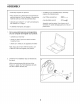
PART iDENTiFiCATiON CHART Use the drawings below to identify the small parts needed for assembly. The number in parentheses below each drawing is the key number of the part, from the PART LIST near the end of this manual. The number following the key number is the quantity needed for assembly. Note: If a part is not in the hardware kit, check to see if it has been preassembled. Extra parts may be included, if a part is missing, please call 1=888=533=1333.
ASSEMBLY Assembly requires two persons. In addition to the included tool(s), assembly requires the following tools: Place all parts in a cleared area and remove the packing materials. Do not dispose of the packing materials until you finish all assembly steps. one Phillips screwdriver (]_====_ one adjustable wrench Left parts are marked "L" or "Left" and right parts are marked "R" or "Right." Assembly may be easier if you have a set of wrenches. To avoid damaging parts, do not use power tools.
3. Orient the Rear Stabilizer (31) and the Carriage Rail (9) as shown. 3 9 Attach the Rear Stabilizer (31) to the Carriage Rail (9) with three M8 x 36mm Screws (26); do not tighten the Screws yet. . Tip: It may be helpful to loosen the four M6 × 40ram Screws (42) in the Seat Frame (7) before you begin this step. Retighten the Screws after you complete this step. 3 14 Partially tighten the Adjustment Knob (14)into the Seat Carriage (3).
6. Tighten the Adjustment Knob (14). 6 Attach a Bumper (24) to the underside of the Carriage Rail (9) with an M4 x 16mm Screw (56). I 24 56 . Slide the Carriage Rail (9) onto the Frame (1). Attach the Carriage Rail with six M8 x 16mm Screws (55); start all of the Screws, and then tighten them. 55 . Make sure that both ends of the Rear Stabilizer (31) are touching the floor. Then, tighten the three M8 x 36mm Screws (26) in the Rear Stabilizer. 15 Orient the Rear Shield (15) as shown.
. Attach the Backrest (6) to the Backrest Frame (5) with four M6 x 36mm Screws (22); start all of the Screws, and then tighten them. 9 10. Orient the Upright (2) as shown. Have a second person hold the Upright near the Frame (1). 10 55 Set the Upright (2) on the Frame (1). Attach the Upright with four M8 x 16mm Screws (55); start all of the Screws, and then tighten them. / 11. Locate the wire tie inside the Upright (2). Tie the lower end of the wire tie to the end of the Wire Harness (53).
12. Orient the Shield Cover (12) as shown. Insert the Wire Harness (53) upward through the Shield Cover. 12 Slide the Shield Cover (12) onto the Upright (2). Then, press the Shield Cover into the Right and Left Shields (38, 39). 38, 39 13. While a second person holds the Handlebar (13) near the Upright (2), insert the Wire Harness (53) upward through the bracket on the Handlebar. 13 53 Tip: Avoid Handlebar Handlebar start all of pinching the wires. Insert the (13) into the Upright (2).
14. The Console (4) can use four D batteries (not included); alkaline batteries are recommended. Do not use old and new batteries together or alkaline, standard, and rechargeable batteries together, iMPORTANT: if the Console has been exposed to cold temperatures, allow it to warm to room temperature before you insert batteries. Otherwise, you may damage the console displays or other electronic components.
16. Identify the Right Pedal (36). 16 Using an adjustable wrench, firmly tighten the Right Pedal (36) clockwise into the right side of the Crank (43). Firmly tighten the Left Pedal (not shown) counterclockwise into the left side of the Crank (not shown). Strap Adjust the right strap to the desired position, and press the ends of the straps onto the tabs on the Right Pedal (36). Adjust the strap on the Left Pedal (not shown) in the same way. Tab 17.
HOW TO USE THE EXERCISE BiKE HOW TO ADJUST THE SEAT CARRIAGE HOW TO LEVEL THE EXERCISE BiKE To adjust the position of the seat If the exercise bike rocks slightly on your floor during use, turn one or both of the leveling caps on the rear stabilizer until the carriage, loosen the adjustment knob, move the seat carriage forward or backward to the desired position, and then firmly tighten the adjustment knob. rocking motion is eliminated.
CONSOLE DIAGRAM mmmm =M=M. RESISTANCE TIME DISTANCE DIGITAL RESISTANCE FEATURES OF THE CONSOLE You can even connect your MP3 player or CD player to the console sound system and listen to your favorite music or audio books while you exercise. The advanced console offers an array of features designed to make your workouts more effective and enjoyable. To use the manual mode, see page 15. To use a preset workout, see page 16. To use the sound system, see page 17. To use the settings mode, see page 17.
HOW TO USE THE MANUAL MODE 1. Profile--When a workout is selected, this display mode will show a profile of the resistance settings of the workout. Turn on the console. Press any button or begin pedaling to turn on the console. Pulse--This display mode will show your heart rate when you use the handgrip heart rate monitor (see step 5). When you turn on the console, the display will turn on. A tone will sound and the console will be ready for use. 2.
5. Measure your heart rate if desired. HOW TO USE A PRESET WORKOUT if there are sheets of 1. plastic on the metal contacts on the Press any button or begin pedaling to turn on the console. handgrip heart rate monitor, remove the plastic, in addition, make sure that your hands are clean. To measure your heart rate, hold the handgrip heart rate monitor with When you turn on the console, the display will turn on. A tone will sound and the console will be ready for use. Contacts 2.
HOW TO USE THE SOUND SYSTEM At the end of each segment of the workout, a series of tones will sound and the next segment of the profile will begin to flash. If a different resistance level is programmed for the next segment, the resistance level will appear in the display for a few seconds to alert you. The resistance of the pedals will then change. To play music or audio books through the console sound system while you exercise, plug a 3.5 mm male to 3.
FCC iNFORMATiON This equipment has been tested and found to comply with the limits for a Class B digital device, pursuant to part 15 of the FCC Rules. These limits are designed to provide reasonable protection against harmful interference in a residential installation. This equipment generates, uses, and can radiate radio frequency energy and, if not installed and used in accordance with the instructions, may cause harmful interference to radio communications.
MAINTENANCE AND TROUBLESHOOTING Inspect and tighten all parts of the exercise bike regularly. Replace any worn parts immediately. Next, locate the Reed Switch (46). Loosen, but do not remove, the M4 x 19mm Screw (18). To clean the exercise bike, use a damp cloth and a small amount of mild soap. IMPORTANT: To avoid damage to the console, keep liquids away from the console and keep the console out of direct sunlight. CONSOLE TROUBLESHOOTING Most console problems are the result of low batteries.
HOW TO ADJUST THE DRIVE BELT Hold the two M8 Locknuts (57) and loosen the two M8 x 16mm Flat Head Screws (34). Next, loosen the M10 x 50mm Hex Screw (30) until the Drive Belt (23) is tight. Then, hold the Locknuts and tighten the Flat Head Screws. If you can feel the pedals slip while you are pedaling, even when the resistance is adjusted to the highest level, the drive belt may need to be adjusted.
EXERCISE GUiDELiNES Burning Fat--To burn fat effectively, you must exercise at a low intensity level for a sustained period of time. During the first few minutes of exercise, your body uses carbohydrate calories for energy. Only after the first few minutes of exercise does your body begin to use stored fat calories for energy. If your goal is to burn fat, adjust the intensity of your exercise until your heart rate is near the lowest number in your training zone.
PART LIST Key No. Qty. 1 2 3 4 5 6 7 8 9 10 11 12 13 14 15 16 17 18 19 20 21 22 23 24 25 26 27 28 29 30 31 1 1 1 1 1 1 1 1 1 2 4 1 1 1 1 2 4 7 2 1 4 4 1 3 5 3 1 2 1 1 1 Model No. 831.21911.0 R0813C Description Key No. Qty.
m X "U r'- 25 56 0 28 m 42 1 m 19 59 1 Z 0 45 17 53 18 tO t_ 41 16 22 16 14.
Your Home iiiiiiiiiiiiiiiiiiiiii_ii!; _ iiiiiiiiiiiiiiiiiiii!; _ For repair--in your home--of all major brand appliances, lawn and garden equipment, iiiiiiiiiiiiiiiiii_ _ iiiiiiiiiiiiiiiiii_ _ or heating and cooling systems, no matter who made it, no matter who sold it! iiiiiiiiiiiiiiiiiii iiiiiiiiiiiiiiiiiii iiiiiiiiiiiiiiiiiiiFor the replacement parts, accessories, and user's manuals that you need to do-it-yourself.