Model No. 831.23943.5 Serial No, Write the serial number in the space above for reference. 5 Serial Number Fs Decal Assembly + Operation Maintenance + Part List and Drawing Sears, Roebuck and Co. Hoffman Estates, IL 60179 CAUTION Head all precautions and instruct: sons in this manual bolero nixing this equipment. Keep this manual fof fire reference.
TABLE OF CONTENTS WARNING DECAL PLACEMENT . ee . Cee . 4 IMPORTANT PRECAUTIONS BEFORE YOU BEGIN. . . PART IDENTITY FIXATION CHART. ASSEMBLY. HOW TO USE THE ELLIPTICAL MAINTENANCE AND TROUBLESHOOTING 18 EXERCISE GUIDELINES... ..20 PART LIST C21 EXPLODED DRAWING. . FEO OOO 22 HOW TO CONTACT CUSTOMER CARE. Back Cover 90 DAY FULL WARRANTY... . ee eee . Cee . Back Cover WARNING DECAL PLACEMENT This drawing shows the location(s) of the warning decal(s).
IMPORTANT PRECAUTIONS A WARNING * To reduce the risk of serious injury, read all important precautions and instructions in this manual and all warnings on your elliptical before using your elliptical. Sears assumes no responsibility for personal injury or property damage sustained by or through the use of this product, 1. iris the responsibility of the owner fo ensure that all users of the elliptical are adequately informed of alt precautions. 2.
BEFORE YOU BEGIN Thank you for purchasing the PROFORM® 390 E elliptical, The 390 E elliptical provides an array of features designed to make your workouts at home more effective and enjoyable For your benefit, read this manual carefully before you use the elliptical.
PART IDENTIFICATION CHART Use the drawings below to identify the small parts needed for assembly. The number in parentheses below each drawing is the key number of the part, from the PART LIST near the end of this manual. The number following the key number is the quantity needed for assembly. Note: If a part is not In the hardware kit, check to see if it has been reassembled. Extra parts may be included.
ASSEMBLY « Assembly requires two persons. « Place all pairs in a cleared area and remove the packing materials. Do not dispose of the packing materials until you finish all assembly steps. + Left parts are marked “L” or “Left” and right parts are marked “R” or “Right.” To identify small parts, see page 5.
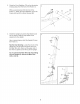
3. Orient the Front Stabilizer (73) so that the sticker 3 is facing away from the front of the Frame (1). While a second person lifts the front of the Frame (1). attach the Front Stabilizer (73) fo the Frame with two M10 x 85mm Screws (82). 4. Orient the Upright (2) and the Top Shield Cover (37) as shown. Slide the Top Shield Cover upward onto the Upright. Have a second person hold the Upright (2) near the Frame (1). See the inset drawing. Locate the wire tie in the Upright {2}.
5. Slide the Upright (2) onto the Frame (1). Tip: Have a second person hold the Top Shield Cover (37) out of the way, Tip: Avoid pinching the Main Wire (42). Attach the Upright (2) with four M10 x 20mm Screws {79} and four M10 Split Washers (78), start all the Screws, and then lighten them, Then, slide the Top Shield Cover (37) downward and press it into the Frame (1). See the upper drawing.
7. The Console (4) can use four D batteries (not included); alkaline batteries are recommended. Do not use old and new batteries together or alkaline, standard. and rechargeable batteries together. IMPORTANT: if the Console has been exposed to cold temperatures, allow it to warm to room temperature before you insert austerities. Otherwise, you may damage the console displays or other electronic components. Remove the screws and the battery covers. and insert batteries info the battery compartments.
§. Attach the Console Cover (32) to the back of the Console (4) with two M4 x 48mm Screws (89). 10. identify the Left and Right Upper Body Arms (8, 9}, and orient them as shown, Orient the Left Sipper Body Arm (8) and an Upper Brady Leg (8) as shown, Make sure that the hexagonal holes are in the indicated location, insert the Left Upper Body Arm (8) into the Upper Body Leg (8). Attach the Left Upper Body Arm (8) with two MB x 45mm Bolts (76) and two M8 Jam Nuts (77).
. Using a plastic bag to keep your fingers clean, apply a generous amount of the included grease to the axles on the Upright (2). Orient the Left and Right Upper Body Arms (8. 9) as shown, and slide them onto the left and right sides of the Upright (2). Attach each Upper Body Arm (8, 9) with an M8 x 20mm Screw (80) and an M8 Washer (33). 12. Apply a small amount of grease to a Shoulder I Bolt (31).
13. 14. 15. Bee the inset drawing. Identify a Pivot Cover A {18}, which has hooks, and a Pivot Cover B (22), which has tabs. Press the Pivot Cover A {19) and the Pivot Cover B {22) together around the Right Upper Body Arm (9). Repeat this step on the other side of the elliptical. Tip: Make sure that the Pivot Covers (18, 22) are positioned as shown. Attach the Rear Upright Cover (3) to the Upright {2) with three M4 x 16mm Screws (92).
18. 17. identify the Right Pedal (13), and orient it as shown. Attach the Right Pedal (13) to the Right Pedal Arm (49) with three M10 x 48mm Screws (75) and three M10 Split Washers (78): start all the Screws, and then tighten them. Make sure to use the center hole and the two outer holes to attach the Right Pedal. Attach the Left Pedal (not shown) to the Left Pedal Arm {not shown} in the same way. Press the Rear Shield Cover (59) onto the Left and Right Shields (44, 45} 16 18.
HOW TO USE THE ELLIPTICAL HOW TO MOVE THE ELLIPTICAL Due to the size and weight of the elliptical, moving it requires two persons, Stand in front of the elliptical, hold the upright, and place one foot against ane of the front wheels.
CONSOLE DIAGRAM WEIGHT LOSS alt, lll il PERFORMANCE J ils Jill All [weigh T | Ali arm A all alk | ve | iPod | all cone | 0 0250) DISTANCE SPEED | RESTS. FEATURES OF THE CONSOLE The advanced console offers an array of features designed to make your workouts more effective and enjoyable. When you use the manual mode of the console, you can change the resistance of the pedals with the touch of a button. As you exercise, the console will provide continuous exercise feedback.
HOW TO USE THE MANUAL MODE 1. Turn on the console. Press any bunion or begin pedaling to turn on the console. When you turn on the console, the display will light. One will sound and the console will be ready for use. Select the manual mode. When you turn on the console, the manual mode will be selected.
7. When you are finished exercising, the console will turn off automatically. if the pedals do not move for several seconds, a series of tones will sound, the console will pause, and the time will flash in the display. if the pedals do not move for several minutes. the console will turn off and the display will be reset. HOW TO USE A PRESET WORKOUT 1. Turn on the console. See step 1 on page 16. 2. Select a preset workout. few seconds to alert you. The resistance of the pedals will then change.
MAINTENANCE AND TROUT MAINTENANCE Regular maintenance is important for optimal performance and fo reduce wear. inspect and properly tighten all parts each time the elliptical is used Replace any worn parts immediately, To clean the elliptical, use a dap cloth and a small amount of mild soap.
HOW TO ADJUST THE REED SWITCH If the console does not display correct feedback, the reed switch should be adjusted. To adjust the reed switch, you must remove the right disc cover and the right pedal disc. Using a standard screwdriver. remove the right Disc Cover {18}. Then, remove the M8 x 12mm Screws (81) from the Right Pedal Disc (27), and gently rotate the Right Pedal Disc out of the way. Locate the Reed Switch (58). Loosen, but do not remove, the M4 x 16mm Screw (92).
EXERCISE GUIDELINES A WANING sobs tie Or any exercise program, consult yous phys can. This is especially unimportant for persons O¥ET age 35 of persons with per-existing health problems, The hear! rate monitor ls not a medical advice, Various factions may affect (he so curacy of Heart rate readings. The heap! rate monitor [= intended only as an exercise aid in determine. ing heart rate te in general, These guidelines will help you to plan your exercise program.
PART LIST Key No. Qty.
Part No. 376505 RO915A Get it fixed, at your home or ours! Your Home For repair—in your home of all major brand appliances, lawn and garden equipment, or heating and cooling systems, no matter who made it, no matter who sold it! For the replacement parts, accessories, and user's manuals that you need to do-it-yourself, For Sears professional installation of home appliances and items like garage door openers and water heaters. 1-800-4-MY-HOME® (1-800-469-4663) Call anytime, day or night and Canada) www.