Model No. 831.24966.1 Serial No. Write the serial number in the space above for reference. Decal • Assembly • Operation • Maintenance • Part List and Drawing Sears, Roebuck and Co.
TABLE OF CONTENTS WARNING DECAL PLACEMENT .............................................................. IMPORTANT PRECAUTIONS ................................................................ BEFORE YOU BEGIN ...................................................................... ASSEMBLY ............................................................................... OPERATION AND ADJUSTMENT ............................................................ HOW TO FOLD AND MOVE THE TREADMILL ......................
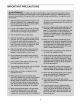
iMPORTANT PRECAUTIONS 3
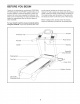
BEFORE YOU BEGIN Thank you for selecting the revolutionary PROFORM ® XP 690T treadmill. The XP 690T treadmill offers an im- ing this manual, please see the back cover of this manual. To help us assist you, please note the product model number and serial number before contacting us. The model number and the location of the serial number decal are shown on the front cover of this manual. pressive selection of features designed to make your workouts at home more enjoyable and effective.
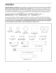
ASSEMBLY Assembly requires two persons. Set the treadmill in a cleared area and remove all packing materials. Do not dispose of the packing materials until assembly is completed. Note: The underside of the treadmill walking belt is coated with high-performance lubricant. During shipping, some lubricant may be transferred to the top of the walking belt or the shipping carton. This is normal and does not affect treadmill performance.
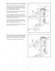
1. Make sure that the power cord is unplugged. With the help of a second person, carefully tip the treadmill onto its left side. Partially fold the Frame (55) so that the treadmill is more stable; do not fully fold the Frame yet. Hole 90 Remove and discard the two indicated bolts (A) and the shipping bracket (B). Cut the shipping tie securing the Upright Wire (87) to the Base (95). Locate a plastic tie in the indicated hole in the Base, and use the tie to pull the Upright Wire out of the hole.
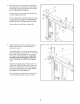
3. IdentifytheRightUpright(85)andthe Right UprightSpacer(91),whicharemarkedwith "Right"stickers.AligntheovalholeintheRight UprightSpacerwiththeovalholeintheBase (95).Iftheholesdonotlineup,turnthe Right UprightSpacerandtryagain. 3 85 87 Insertthe UprightWire(87)throughtheRight UprightSpacer(91)asshown.Setthe Right UprightSpacerontheBase(95). Havea secondpersonholdthe RightUpright (85)neartheBase(95).Seethe insetdrawing. Tiethewiretie intheRightUprightsecurely aroundtheendoftheUprightWire(87).
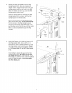
5. Withthe helpofa secondperson,carefullytip thetreadmillontoitsrightside.Partiallyfoldthe Frame(55)sothatthetreadmillis morestable; do not fully fold the Frameyet. 5 B Removeanddiscardthetwoindicated bolts(A) andtheshippingbracket(B). Attacha Wheel(96)totheBase(95)witha 3/8" x2" Bolt(8)anda 3/8"Nut(10).Do notovertightenthe Nut;the Wheelmustturn freely. 89 55 Pressa BaseCap(89)intothe Base(95).
7. Insert the bracket on the Left Handrail (82) into the Left Upright (84). 7 102 Insert the Upright Wire (87) several inches downward into the Right Upright (85); make sure that the wire tie does not fall into the Right Upright. Then, insert the Right Handrail (83) into the Right Upright. Be careful not to pinch the Upright Wire. 82 Orient the Console Frame (102) as shown, with the welded nuts on the bottom. Insert the ends of the Console Frame into the Left and Right Handrails (82, 83).
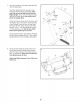
9. With the help of a second person, hold the handrail assembly (B) upside-down near the console assembly (A). Connect the Console Ground Wires (6) in the handrail assembly to the ground wires in the console assembly. 9 Insert the console wire (C) into the track in the console assembly (A). Insert the Ground Wires (6) into the hole in the console assembly (A) as you set the handrail assembly (B) in the console assembly. Make sure that the console wire (C) stays in the track.
11. Slide the Left Upright Cover (80) onto the Left Upright (84). Slide the Right Upright Cover (86) onto the Right Upright (85). 85 12. With the help of a second person, hold the console assembly (A) near the Right Upright (85) and the Left Upright (not shown), Insert the Upright Wire (87) into the hole in the bottom of the Right Handrail and out of the end as shown. 12 Notch Connect the Upright Wire (87) to the console wire (C), See the inset drawing.
. Attach the console assembly (A) to the Left Upright (84) and the Right Upright (85) with six 5/16" x 1" Patch Bolts (4) and six 5/16" Star Washers (13), Start all six Patch Bolts before tightening any of them. 13 A See steps 4 and 6. Tighten the 3/8" x 4 1/4" Patch Bolts (7). I 13 13 13 84 m 14. Raise the Frame (55) to the position shown. Have a second person hold the Frame until this step is completed.
OPERATION THE PRE-LUBRICATED AND ADJUSTMENT WALKING BELT tric shock. This product is equipped with a cord having an equipment-grounding conductor and a grounding plug. Plug the power cord into a surge suppressor, and plug the surge suppressor into an appropriate outlet that is properly installed and grounded in accordance with all local codes and ordinances. IMPORTANT: The treadmill is not compatible with GFCl-equipped outlets. Your treadmill features a walking belt coated with highperformance lubricant.
CONSOLE DIAGRAM !,!,0 _0,0 YZ %0 / / 7oo / 1 2 \ \ FEATURES OF THE CONSOLE You can even listen to your favorite workout music or audio books with the console's stereo sound system. The treadmill console offers an impressive array of features designed to make your workouts more effective and enjoyable.
HOW TO TURN ON THE POWER HOW TO USE THE MANUAL MODE iMPORTANT: if the treadmill has been cold temperatures, allow it to warm to perature before turning on the power, do this, you may damage the console other electrical components. Plug in the power cord (see page 14). Next, locate the reset/off circuit breaker on the treadmill exposed to room temif you do not displays or 1. insert the key into the console. See HOW TO TURN ON THE POWER at the left. 2. Select the manual mode.
4. Change the incline of the treadmill as desired. 6. To change the incline of the treadmill, press the Incline increase or decrease button, or one of the incline buttons numbered 0 to 10. Each time you press one of the buttons, the incline will gradually change until it reaches the selected incline setting. . Measure your heart rate if desired. Before using the handgrip pulse sensor, remove the sheets of clear plastic from the metal contacts. In addition, make sure that your hands are clean.
HOW TO USE A PRESET WORKOUT 1. At the end of each segment, a series of tones will sound. If a new speed and/or incline setting is programmed for the next segment, the speed and/or incline will appear in the display and the treadmill will automatically adjust to the new speed and incline settings. Insert the key into the console. See HOW TO TURN ON THE POWER on page 16. 2. Select a preset workout.
HOW TO USE THE IFIT TRAiNiNG MODE The display will show the selected unit of measurement. To change the unit of measurement, press the Speed increase button. To view distance in miles, select ENGLISH. To view distance in kilometers, select METRIC. The optional iFit Live module allows your treadmill to communicate with your wireless network and unlocks exciting new features. For example, you can download personalized workouts and track and analyze your workout results on the iFit Live website.
HOW TO FOLD AND MOVE THE TREADMILL HOW TO FOLD THE TREADMILL FOR STORAGE Before folding the treadmill, adjust the incline to the lowest position, if you do not do this, you may damage the treadmill when you fold it. Remove the key and unplug the power cord. CAUTION: You must be able to safely lift 45 Ibs. (20 kg) to raise, lower, or move the treadmill. Frame 1. Hold the metal frame firmly in the location shown by the arrow at the right.
HOW TO LOWER THE TREADMILL FOR USE 1. Hold the upper end of the treadmill with your right hand. Pull the latch knob to the left and hold it. It may be necessary to push the frame forward as you pull the knob to the left. Pivot the frame downward and release the latch knob. Latch 2. Hold the metal frame firmly with both hands and lower it to the floor. CAUTION: Do not grip only the plastic foot rails or drop the frame to the floor. Bend your legs and keep your back straight.
TROUBLESHOOTING Most treadmill problems can be solved by following the simple steps below. Find the symptom that applies, and follow the steps listed, if further assistance is needed, see the back cover of this manual. PROBLEM: The power does not turn on SOLUTION: a. Make sure that the power cord is plugged into a surge suppressor, and that the surge suppressor is plugged into a properly grounded outlet (see page 14).
Remove the three #8 x 3/4" Screws (1) and carefully pivot the Motor Hood (62) off. 1 62 Locate the Reed Switch (73) and the Magnet (47) on the left side of the Pulley (48). Turn the Pulley until the Magnet is aligned with the Reed Switch. Make sure that the gap between the Magnet and the Reed Switch is about 1/8 in. (3 ram).
PROBLEM: The walking SOLUTION: a. If the walking belt is off-center, first remove the key and UNPLUG THE POWER CORD. If the walking belt has shifted to the left, use the hex key to turn the left idler roller bolt clockwise 1/2 of a turn; if the walking belt has shifted to the right, turn the left idler roller bolt counterclockwise 1/2 of a turn, Be careful not to overtighten the walking belt. Then, plug in the power cord, insert the key, and run the treadmill for a few minutes.
EXERCISE GUiDELiNES Burning Fat--To burn fat effectively, you must exercise at a low intensity level for a sustained period of time, During the first few minutes of exercise, your body uses carbohydrate calories for energy.
PART LISTmModel No. 831.24966.1 R0110A To locate the parts listed below, see the EXPLODED DRAWING near the end of this manual. Key No. Qty. 1 2 3 4 2 32 4 5 6 7 Description Key No. Qty.
Key No. Qty. Description Key No. Qty. Description 101 102 1 1 Console Console Frame 106 107 1 4 Console Base #8 x 1" Screw 103 104 105 1 1 2 Left Accessory Tray Right Accessory Tray Console Clamp 108 * 1 - Left Speaker User's Manual Note: Specifications are subject to change without notice. For information about ordering replacement parts, see the back cover of this manual, if a part is missing, call 1-888-533-1333. *These parts are not illustrated.
EXPLODED DRAWING AmlVlodel No. 831.24966.1 '_- co oJ R0110A L_ / /' H o oJ LO O0 LO LO LO ._.
EXPLODED DRAWING BmlVlodel No. 831.24966.
EXPLODED DRAWING C--lVlodel No. 831.24966.1 RolloA 83 81 7 13 88 11 ._-89 85 35 27 86 14 80 27 95 I ¢_.
EXPLODED DRAWING D--IVlodel No. 831.24966.
Your Home iiiiiiiiiiiiiiiiiiii,i For repair--in iiiiiiiiiiii@ _ your home--of all major brand appliances, lawn and garden equipment, ® Registered Trademark / TMTrademark / sMService Mark of Sears Brands, LLC ® Marca Registrada / TMMarca de F#,brica / SMMarca de Servicio de Sears Brands, LLC f ONE YEAR FULL WARRANTY f If this Sears Treadmill Exerciser fails due to a defect in material or workmanship within 1 year of the date of purchase, call 1-800-4-MY-HOME ®(1-800-469-4663) to arrange for free re