
Manual

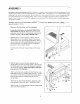
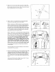


3. AttachtheLatchAssembly(82)totheLeftUpright(84)
withthetwoLatchScrews(134)StartbothLatchScrews
beforetighteningeitherofthem.Note:TheLatchScrews
maybepreattachedtotheLeftUpright
134
82
4. Refertostep6andlocatethefourUprightBolts(86).
LoosentheUprightBoltstwotothreeturns.
Refertodrawing4c.Withthehelpofasecondperson,
holdtheConsoleBase(101)neartheUprights(80,84).
LookundertheConsoleBaseandlocatethewireson
thesidesoftheConsoleBase.Makesurethatthewires
arenotroutedthroughtheopeningsfortheTrays(109,
111).Drawing4ashowsthecorrectrouteforthewires.
Drawing4bshowsanincorrectroute.
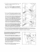
Refertodrawing4c.CuttheplastictiesholdingtheWire
Harness(74)andthePulseWire(70)intheUprights(80,
84).ConnecttheWireHarnessandthePulseWiretothe
wiresonthesidesoftheConsoleBase(101).Make sure
to connect the connectors properly (see the inset
drawings). IF THE CONNECTORS ARE NOT CON-
NECTED PROPERLY, THE CONSOLE MAY BE DAM-
AGED WHEN THE POWER IS TURNED ON. The con-
nectors should slide together easily and snap into
place. If the connectors do not slide together easily and
snap into place, turn one connector and try again. Insert
the excess Wire Harness and Pulse Wire up into the
Console Base.
Press the Right and Left Top Endcaps (75, 81) into the
Uprights (80, 84) as shown.
4a
Correct Incorrect
4c
io
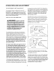
5. Set the Console Base (101) on the Uprights (80, 84). Be
careful not to pinch the Wires (not shown) in the
Uprights. Attach the Console Base to each Upright with
two Console Bolts (76) and two Internal Star Washers
(77); start all four Console Bolts before tightening any of
them.
Make sure that the Left and Right Trays (109, 111) are
pressed into the Console Base (101).
5
7E
101
76