¨ Patent Pending Model No. PFSY64390 Serial No. The serial number is found in the location shown below. Write the serial number in the space above. USERÕS MANUAL Serial Number Decal QUESTIONS? As a manufacturer, we are committed to providing complete customer satisfaction. If you have questions or if there are missing parts, we will guarantee complete satisfaction through direct assistance from our factory. TO AVOID UNNECESSARY DELAYS, PLEASE CALL DIRECT TO OUR TOLL-FREE CUSTOMER HOT LINE.
Table of Contents Important Precautions . . . . . . . . . . . . . . . . . . . . . . . . . . . . . . . . . . . . . . . . . . . . . . . . . . . . . . . . . . . . . . . . . . . 2 Before You Begin . . . . . . . . . . . . . . . . . . . . . . . . . . . . . . . . . . . . . . . . . . . . . . . . . . . . . . . . . . . . . . . . . . . . . . 3 Assembly . . . . . . . . . . . . . . . . . . . . . . . . . . . . . . . . . . . . . . . . . . . . . . . . . . . . . . . . . . . . . . . . . . . . . . . . . . . .
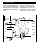
Before You Begin Thank you for selecting the versatile PROFORM¨ 875 home gym. The PROFORM¨ 875 offers a unique selection of weight stations designed to develop every major muscle group of the body. Whether your goal is to tone your body, build dramatic muscle size and strength, or improve your cardiovascular system, the PROFORM¨ 875 will help you to achieve the results you want. additional questions, please call our Customer Service Department toll-free at 1-800-999-3756, Monday through Friday, 6 a.m.
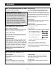
Assembly Note: This introduction will save you more time than it takes to read it! Identifying Parts To help you identify the small parts used in assembly, we have included a PART IDENTIFICATION CHART in the center of this manual. Place the chart on the floor and use it to quickly identify parts as you open the packages for each step. Note: Some small parts may have been pre-attached for shipping. If a part is not in the parts bag, check to see if it has been pre-attached.
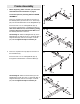
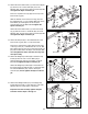
1a Frame Assembly 28 1. Before beginning, make sure that you have read and understood the information on page 4. 85 85 4 Locate and open the parts bag labeled ÒFRAME ASSEMBLY.Ó 92 Press a 2Ó Square Inner Cap (28) into each end of the Butterfly Base (4). Press two 2Ó x 4Ó Inner Caps (85) into the indicated bracket on the Weight Base (5). 5 92 28 Insert four 5/16Ó x 2 1/2Ó Carriage Bolts (92) up through the indicated holes in the Butterfly Base (4).
3. Place the bracket on the lower end of the Butterfly Upright (1) over the indicated 5/16Ó x 2 1/2Ó Carriage Bolts (92) in the Butterfly Base (4). Hand tighten two 5/16Ó Nylon Locknuts (64) onto the Bolts. Do not tighten the Nylon Locknuts yet. 3 1 64 4 92 4. Press three 2Ó Square Inner Caps (28) into the Butterfly Top Frame (33).
6. Slide the bracket on the Butterfly Front Leg (3) onto the two indicated 5/16Ó x 2 1/2Ó Carriage Bolts (92) in the Butterfly Base (4). Hand tighten two 5/16Ó Nylon Locknuts (64) onto the Bolts. Do not tighten the Nylon Locknuts yet. 6 3 14 64 36 Attach the Butterfly Seat Frame (14) to the Butterfly Front Leg (3) with two 5/16Ó x 2 3/4Ó Bolts (89), two 5/16Ó Washers (36), and two 5/16Ó Nylon Locknuts (64). Do not tighten the Nylon Locknuts yet. 89 64 64 4 92 7.
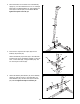
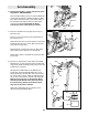
9. Lubricate the insides of the holes in the Top Weight assembly (104). Press the Weight Tube Bumper (18) into the indicated end of the Weight Tube (17). 9 15 Slide the Weight Tube (17) and the Top Weight assembly (104) onto the Weight Guides (15). Insert the Weight Tube into the stack of Weights (21). Lubricate 104 17 18 Hole 21 10. Press a 2Ó Square Inner Cap (28) into the each of the Press Top Frame (9).
12. Attach the Press Seat Frame (7) to the Press Upright (2) with two 5/16Ó x 2 3/4Ó Bolts (89), two 5/16Ó Washers (36), and two 5/16Ó Nylon Locknuts (64). Do not tighten the Nylon Locknuts yet. 12 2 64 89 64 Press a 2Ó Square Inner Cap (28) into the top of the Press Front Leg (20). Slide the bracket on the Press Front Leg (20) onto the indicated 5/16Ó x 2 1/2Ó Carriage Bolts (92) in the Press Base (6). Hand tighten two 5/16Ó Nylon Locknuts (64) onto the Bolts. Do not tighten the Nylon Locknuts yet.
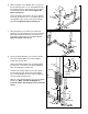
16 Arm Assembly 8 16. Press Arm AssemblyÑLocate and open the parts bag labeled ÒARM ASSEMBLY.Ó Press a Plastic Bushing (100) onto each welded tube on the Press Frame (8). Lubricate the 3/8Ó x 8Ó Bolt (52). Attach the Press Frame to the welded tubes on the Press Base (6) with the Bolt and a 3/8Ó Nylon Locknut (50). Do not overtighten the Nylon Locknut; the Press Frame must pivot easily. 50 6 Lubricate Welded Tube 100 17. Press a 2Ó Square Inner Cap (28) into the top of a Press Arm (77).
19 Cable Assembly 84 Bracket 19. Locate and open the parts bag labeled ÒCable Assembly and Pulleys.Ó For Cable identification and routing during steps 19 to 49, refer to the Cable Diagram and Cable ID Chart on page 23 and 24. Identify the Butterfly Cable (73); it is approximately 65Ó long and it has a closed loop on each end. Attach one end of the Butterfly Cable to the bracket on the Left Butterfly Arm (10) with a 3/8Ó x 1Ó Bolt (84) and two 3/8Ó Nylon Jam Nuts (63).
23. Attach the Butterfly Cable (73) to the bracket on the Right Butterfly Arm (11) with a 3/8Ó x 1Ó Bolt (84) and two 3/8Ó Nylon Jam Nuts (63). Note: The loop on the Cable and the two Nylon Jam Nuts must be underneath the bracket. 23 84 Bracket 11 63 73 24. Identify the Weight Cable (72); it is approximately 117 3/4Ó long and it has a closed loop on one end and a bolt on the other end.
27. Attach the bolt at the end of the Weight Cable (72), the 1/2Ó Plain Nut (107), the 1/2Ó Flat Washer (86), and the Long Weight Spacer (98) to the Weight Tube (17) in the order shown. 27 Note: The bolt at the end of the Weight Cable (72) is one of the means for tightening the Cables (72, 73, 74, and 75).
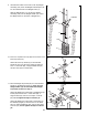
30. Remove both 3 1/2Ó Pulleys (24) and the Cable Trap (25) from the pre-assembled Pulley Plates (23). 30 74 Wrap the High Cable (73) around a 3 1/2Ó Pulley (24) in the direction shown. Attach the Pulley and the Cable Trap (25) to the top hole in the Pulley Plates (23) with a 3/8Ó x 2Ó Bolt (54) and a 3/8Ó Nylon Locknut (50). Make sure the Cable Trap and Pulley Plates are oriented as shown in the drawing. 24 25 50 54 23 31. Wrap the High Cable (74) around a 3 1/2Ó Pulley (24) in the direction shown.
34. Wrap the Low Cable (75) around a 3 1/2Ó Pulley (24) in the direction shown. Attach the Pulley and a Cable Trap (25) to the indicated hole in the Butterfly Upright (1) with a 3/8Ó x 3 3/4Ó Bolt (59), a 3/8Ó Flat Washer (48), and a 3/8Ó Nylon Locknut (50). Make sure that the Cable Trap is oriented as shown. 34 1 59 48 25 50 24 75 35. Wrap the Low Cable (75) around a 3 1/2Ó Pulley (24) in the direction shown.
37. Note: For the sake of clarity, the weights are not shown in the following steps. 37 75 Wrap the Low Cable (75) around a 3 1/2Ó Pulley (24) in the direction shown. Attach the Pulley to the indicated bracket on the Weight Base (5) with a 3/8Ó x 1 3/4Ó Bolt (57) and a 3/8Ó Nylon Locknut (50). 24 5 57 Bracket 50 38. Wrap the Low Cable (75) around a 3 1/2Ó Pulley (24) in the direction shown.
40. Wrap the Low Cable (75) around a 3 1/2Ó Pulley (24) in the direction shown. Attach the Pulley to the indicated bracket on the Press Base (6) with a 3/8Ó x 1 3/4Ó Bolt (57) and a 3/8Ó Nylon Locknut (50). 40 75 50 24 57 6 Bracket 41. Important note: Although the following steps are not difficult to perform, the correct routing of the cable is critical. Please make sure that you wrap the cable around the pulleys exactly as shown in each step.
43. Route the Low Cable (75) through the hole in the center of the Press Frame (8). Wrap the Low Cable around a 3 1/2Ó Pulley (24) in the direction shown. Attach the Pulley and a Cable Trap (25) to the indicated hole in the Press Frame (8) with a 3/8Ó x 3 1/2Ó Bolt (56), a 3/8Ó Flat Washer (48), and a 3/8Ó Nylon Locknut (50). Make sure the Cable Trap is oriented as shown. 43 56 48 75 25 8 24 44. Wrap the Low Cable (75) around a 3 1/2Ó Pulley (24) in the direction shown.
47. Route the Low Cable (75) through the hole in the center of the Press Frame (8). Attach the Low Cable to the indicated hole in the Leg Lever (41) with a 3/8Ó x 2 3/4Ó Bolt (46), two 3/8Ó Flat Washers (48), and a 3/8Ó Nylon Jam Nut (63). 47 41 63 Go back to step to step 27 and follow the instructions to tighten the Cables. 8 48 75 48 48. Attach the Shroud (34) to the brackets underneath the Weight Top Frame (66) with two 1/4Ó x 5/8Ó Screws (97). 46 48 66 97 97 Bracket 34 49.
50 Seat Assembly 50. Press a 1Ó x 2Ó Inner Cap (83) into each end of a Backrest Adjustment Frame (70). Press a 1 1/4Ó Inner Cap (35) into the indicated tube on the Backrest Adjustment Frame. 1 12 Identify the Butterfly Backrest (12). It has only two holes in the back. Attach the Butterfly Backrest to the Backrest Adjustment Frame with two 1/4Ó x 1/2Ó Bolts (82) and two 1/4Ó Flat Washers (71).
52. Attach the Curl Pad (91) to the welded plate on the Butterfly Front Leg (3) with two 1/4Ó x 3/4Ó Bolts (49). 52 91 49 53. Press a 1Ó x 2Ó Inner Cap (83) into each end of a Backrest Adjustment Frame (70). Press a 1 1/4Ó Inner Cap (35) into the indicated tube on the Backrest Adjustment Frame. Insert a 1/4Ó x 1 1/2Ó Carriage Bolt (101) into the center hole in a Seat Plate (65). Attach the Seat Plate to the Press Backrest (99) with two 1/4Ó x 3/4Ó Bolts (49).
56. Make sure that all parts are properly tightened. The use of the remaining parts will be explained in ADJUSTMENT, beginning on page 25 of this manual. Before using the home gym, pull each cable a few times to make sure that the cables move smoothly over the pulleys. If one of the cables does not move smoothly, find and correct the problem. IMPORTANT: If the cables are not properly installed, they may be damaged when heavy weight is used.
Cable Diagrams The cable diagrams below and on the next page show the proper routing of the Butterfly Cable (73), the High Cable (74), the Low Cable (75), and the Weight Cable (72). The numbers show the correct route for each Cable. Make sure that the Cables are routed correctly, that the pulleys move smoothly, and that the cable traps do not touch or bind the Cables. Incorrect cable routing can damage the weight system.
Low Cable (75) 3 6 9 4 5 7 2 10 8 11 13 1 12 14 15 24
Adjustment The instructions below describe how each part of the home gym can be adjusted. IMPORTANT: When using an attachment, make sure it is in the correct starting position for the exercise to be performed. If there is any slack in the cables or chain as an exercise is performed, the effectiveness of the exercise will be reduced. Attaching the Lat Bar, Row Bar, Nylon Strap, or Ab Strap to the Low Pulley Station, the High Pulley Station, or the Ab Pulley Station.
Trouble-shooting and Maintenance Inspect and tighten all parts each time you use the home gym. Replace any worn parts immediately. The home gym can be cleaned using a damp cloth and mild non-abrasive detergent. Do not use solvents. Tightening the Cables Woven cable, the type of cable used on the home gym, can stretch slightly when it is first used. If there is slack in the cables before resistance is felt, the cables should be tightened.
Weight Resistance Chart The chart below shows the approximate weight resistance at each exercise station. ÒTopÓ refers to the 6 lb. top weight; the other numbers refer to the 10 lb. weight plates. Note: The actual resistance at each station may vary due to differences in individual weight plates as well as friction between the cables, pulleys, and weight guides. Leg Raise (lbs.) High Pulley (lbs.) Arm Press (lbs.) Ab Pulley (lbs.) Low Pulley (lbs.) Butterfly Arms (lbs.
Part Identification ChartÑModel No.
3/8" x 1" Bolt (84) 3/8" x 7" Bolt (55) 3/8" x 8" Bolt (52) 3/8" x 1 3/4" Bolt (57) 3/8" x 2" Bolt (54) 3/8" x 2 1/2" Bolt (53) 3/8" x 2 3/4" Bolt (46) 3/8" x 3 1/4" Bolt (62) 3/8" x 3 1/2" Bolt (56) 3/8" x 3 3/4" Bolt (59) 3/8" x 4 3/4" Bolt (60)
3/4" Round Inner Cap (43) Retainer Ring (31) 1" Inner Cap (76) 1" Round Outer Cap (38) 1Ó x 2" Inner Cap (83) 1 1/4" Square Inner Cap (35) 2" Square Inner Cap (28)
Part ListÑModel No. PFSY64390 Key No. 1 2 3 4 5 6 7 8 9 10 11 12 13 14 15 16 17 18 19 20 21 22 23 24 25 26 27 28 29 30 31 32 33 34 35 36 37 38 39 40 41 42 43 44 45 46 47 48 49 50 51 52 53 54 Qty.
28 89 11 91 36 3 29 28 88 38 37 54 37 92 24 4 12 10 89 50 35 71 92 14 83 63 73 101 65 68 24 25 75 50 57 78 49 31 84 64 49 71 82 90 88 38 63 73 64 83 13 29 28 28 31 84 64 94 64 50 83 82 70 71 48 28 64 32 24 57 78 48 50 64 48 1 50 64 50 35 82 85 48 59 71 83 27 53 28 89 94 5 28 81 85 50 27 53 50 57 24 64 25 55 89 36 24 48 64 36 50 32 28 33 89 58 19 54 Exploded DrawingÑModel No.
Ordering Replacement Parts To order replacement parts, simply call our Customer Service Department toll-free at 1-800-999-3756, Monday through Friday, 6 a.m. until 6 p.m. Mountain Time (excluding holidays).