
Owner's Manual

10
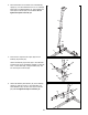
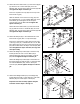
17. Press a 2Ó Square Inner Cap (28) into the top of a
Press Arm (77).
Press a 1Ó Inner Cap (76) into the indicated hole in
the Press Arm (77).
Attach the Press Arm (77) to the bracket on the Press
Frame (8) with two 5/16Ó x 2 3/4Ó Bolts (89) and two
5/16Ó Nylon Locknuts (64).
Wet the handle on each Press Arm (77) with soapy
water. Slide a Press Grip (95) onto the handle.
Repeat these steps to assemble the other Press Arm
(not shown).
17
52
100
6
50
8
28
8
89
64
77
76
95
Welded
Tube
Lubricate
Arm Assembly
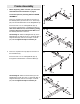
16. Press Arm AssemblyÑLocate and open the parts
bag labeled ÒARM ASSEMBLY.Ó
Press a Plastic Bushing (100) onto each welded tube
on the Press Frame (8). Lubricate the 3/8Ó x 8Ó Bolt
(52). Attach the Press Frame to the welded tubes on
the Press Base (6) with the Bolt and a 3/8Ó Nylon
Locknut (50). Do not overtighten the Nylon
Locknut; the Press Frame must pivot easily.
16
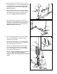
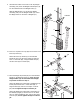
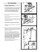
18. Press two 2Ó Square Inner Caps (28) into the Right
Butterfly Arm (11). Wet the lower end of the Arm with
soapy water. Slide a Butterfly Foam Pad (29) onto the
indicated end of the Arm.
Lubricate the indicated axle on the Butterfly Top
Frame (33). Orient the Right Butterfly Arm (11) as
shown and slide it onto the axle. Have a second per-
son hold the Arm in place. Place two Retainer Rings
(31) on top of an inverted 1Ó Round Outer Cap (38).
Make sure that the teeth on the Retainer Rings
bend toward the Round Outer Cap as shown in
the inset drawing. Gently tap the Round Outer
Cap onto the axle with a hammer.
Attach the Left Butterfly Arm (not shown) on the
opposite side as described above.
18
33
38
11
Axle
28
29
28
31
Teeth
Axle
31
38