
Owner's Manual
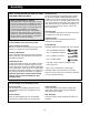

1. Before beginning, make sure that you have read
and understood the information on page 4.
Locate and open the parts bag labeled ÒFRAME
ASSEMBLY.Ó
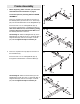
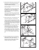
Press a 2Ó Square Inner Cap (28) into each end of
the Butterfly Base (4). Press two 2Ó x 4Ó Inner Caps
(85) into the indicated bracket on the Weight Base (5).
Insert four 5/16Ó x 2 1/2Ó Carriage Bolts (92) up
through the indicated holes in the Butterfly Base (4).
Note: If the Bolts fall out, secure them by putting
a piece of tape over the head of each Bolt. Place
the Butterfly Base flat on the floor.
See drawing 1b. Attach the Weight Base (5) to the
Butterfly Base (4) with two 5/16Ó x 2 3/4Ó Bolts (89), a
Support Plate (94), and two 5/16Ó Nylon Locknuts
(64). Do not tighten the Nylon Locknuts yet.
1a
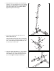
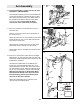
2. Press a 2Ó Square Inner Cap (28) into each end of
the Press Base (6).
Insert four 5/16Ó x 2 1/2Ó Carriage Bolts (92) up
through the indicated holes in the Press Base (6).
See drawing 2b. Attach the Press Base (6) to the
Weight Base (5) with two 5/16Ó x 2 3/4Ó Bolts (89), a
Support Plate (94), and two 5/16Ó Nylon Locknuts
(64). Do not tighten the Nylon Locknuts yet.
2a
2b
5
Frame Assembly
92
4
5
28
85
85
92
28
64
6
89
5
5
92
6
28
28
92
64
94
1b
5
4
89
64
94
64