Model No. PFCCEX34390 Serial No. USER'S MANUAL Serial Number Decal QUESTIONS? As a manufacturer, we are committed to providing complete customer satisfaction. If you have questions, or if there are missing parts, we will guarantee complete satisfaction through direct assistance from our factory. TO AVOID UNNECESSARY DELAYS, PLEASE CALL DIRECT TO OUR TOLL-FREE CUSTOMER HOT LINE. The trained technicians on our customer hot line will provide immediate assistance, free of charge to you.
TABLE OF CONTENTS IMPORTANT PRECAUTIONS . . . . . . . . . . . . . . . . . . . . . . . . . . . . . . . . . . . . . . . . . . . . . . . . . . . . . . . . . . . . .3 BEFORE YOU BEGIN . . . . . . . . . . . . . . . . . . . . . . . . . . . . . . . . . . . . . . . . . . . . . . . . . . . . . . . . . . . . . . . . . . .4 ASSEMBLY . . . . . . . . . . . . . . . . . . . . . . . . . . . . . . . . . . . . . . . . . . . . . . . . . . . . . . . . . . . . . . . . . . . . . . . . . . .5 HOW TO OPERATE THE RECUMBENT CYCLE .
IMPORTANT PRECAUTIONS WARNING: To reduce the risk of serious injury, read the following important precautions before using the recumbent cycle. 1. Read all instructions in this manual before using the recumbent cycle. 7. The cycle should not be used by persons weighing more than 250 pounds (115 kg). 2. It is the responsibility of the owner to ensure that all users of the recumbent cycle are adequately informed of all precautions. Use the recumbent cycle only as described in this manual. 8.
BEFORE YOU BEGIN Department toll-free at 1-888-936-4266, Monday through Friday, 8 a.m. until 6:30 p.m. Eastern Standard Time (excluding holidays). To help us assist you, please mention the product model number and serial number when calling. The model number is PFCCEX34390. The serial number can be found on a decal attached to the recumbent cycle (see the front cover of this manual). Congratulations for selecting the new PROFORM® 985R recumbent cycle.
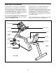
ASSEMBLY Assembly requires two persons. Place all parts of the recumbent cycle in a cleared area and remove the packing materials. Do not dispose of the packing materials until assembly is completed. Assembly requires the included tools and your own adjustable wrench driver . and Phillips screw- Use the part drawings below to identify the small parts used in assembly. The number in parenthesis below each drawing refers to the key number of the part, from the PART LIST in the center of this manual.
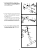
1. Attach the Front Stabilizer (2) to the front of the Frame (1) with two M10 x 75mm Carriage Bolts (72) and two M10 Nylon Locknuts (45). Make sure that the Front Stabilizer is turned so the Wheels (75) are not touching the floor. 1 72 2 75 1 45 2. Slide the Carriage Bar (7) onto the indicated tube on the Frame (1). Attach the Carriage Bar to the Frame with four M10 x 25mm Button Screws (74) and four M10 Split Washers (17).
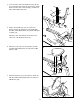
4. Insert the lower end of the Backrest Frame (8) into the Seat Frame (27). Attach the Seat Frame and the Backrest Frame to the Seat Carriage (11) with four M8 x 38mm Button Bolts (24). 4 24 24 27 8 11 5. Slide a Seat Handle (61) onto one side of the Backrest Frame (8). Attach the Seat Handle with two M6 x 38mm Button Bolts (14) and two M6 Nylon Locknuts (15). 5 8 Attach the other Seat Handle (not shown) to the other side of the Backrest Frame (8). 15 14 61 6.
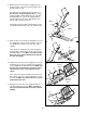
. While another person holds the Upright (6) in the position shown, connect the Extension Wire (18) to the Wire Harness (69). 8 Carefully slide the Upright (6) onto the Frame (1). Be careful to avoid pinching the wires. Loosely thread four M10 x 25mm Button Screws (74) with M10 Split Washers (17) into the Upright and the Frame. Attach the tops of the Side Shields (4, 5) with two M4 x 16mm Screws (21).
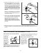
12. Identify the Left Pedal (40) (there is an “L” on the Left Pedal for identification). Using an adjustable wrench, firmly tighten the Left Pedal counterclockwise into the left arm of the Crank (19). Tighten the Right Pedal (not shown) clockwise into the right arm of the Crank. Tighten both Pedals as firmly as possible. Important: After using the recumbent cycle for one week, retighten the Pedals. For best performance, the Pedals must be kept properly tightened.
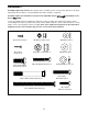
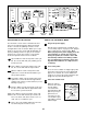
Program Profiles Mode Arrow Resistance Buttons Mode Button On/Reset Button DESCRIPTION OF THE CONSOLE Select Button HOW TO USE THE MANUAL MODE The innovative console offers a manual mode and three preset workout programs. When the manual mode is selected, the pedaling resistance can be changed with a touch of a button. When a preset programs is selected, the console will automatically control the pedaling resistance to give you an effective workout.
4 5 Adjust the pedaling resistance as desired. 6 Measure your heart rate, if desired. As you exercise, adjust the pedaling resistance by pressing the resistance buttons. The indicators on the left side of the Resistance console will show Indicators which resistance level is selected.
program P2, for example, the profile shows that the pedaling resistance will gradually increase during the first ten minutes, and then gradually decrease during the last ten minutes. HOW TO USE A PRESET WORKOUT PROGRAM 1 Plug in the power supply. See step 1 on page 10. 2 4 Turn on the power. As you exercise, the pedaling resistance will periodically change, as shown by the program profiles on the console. The indicators on the left side of the console will show the current resistance level.
CONDITIONING GUIDELINES The following guidelines will help you to plan your exercise program. Remember that proper nutrition and adequate rest are essential for successful results. Fat Burning To burn fat effectively, you must exercise at a relatively low intensity level for a sustained period of time. During the first few minutes of exercise, your body uses easily accessible carbohydrate calories for energy.
CUSTOMER RECORD Model No.: Serial No.
HOW TO ORDER REPLACEMENT PARTS To order replacement parts, call our Customer Service Department toll-free at 1-888-936-4266, Monday through Friday, 8 a.m. until 6:30 p.m. Eastern Standard Time (excluding holidays).
LIMITED WARRANTY ICON Health & Fitness, Inc. (ICON), warrants this product to be free from defects in workmanship and material, under normal use and service conditions, for a period of ninety (90) days from the date of purchase. This warranty extends only to the original purchaser. ICON's obligation under this warranty is limited to replacing or repairing, at ICON's option, the product through one of its authorized service centers.
REMOVE THIS EXPLODED DRAWING AND PART LIST FROM THE MANUAL 34 Save this EXPLODED DRAWING and PART LIST for future reference. Note: Specifications are subject to change without notice. For information about ordering replacement parts, see the back cover of the User’s Manual.
NOTES
1 1 1 1 1 1 1 1 1 2 1 1 1 7 6 1 10 1 1 7 17 3 1 4 8 2 1 2 4 1 1 Frame Front Stabilizer Rear Stabilizer Left Side Shield Right Side Shield Upright Carriage Bar Backrest Frame Console Handlebar Endcap Seat Carriage Seat Backrest M6 x 38mm Button Bolt M6 Nylon Locknut Handlebar M10 Split Washer Extension Wire Pulley/Crank M8 Washer M4 x 16mm Screw M6 Washer Frame Endcap M8 x 38mm Button Bolt M5 x 6mm Screw Seat Carriage Bushing Seat Frame Bushing M6 x 22mm Button Screw Pivot Bushing Magnet Description 32 33
17 2 40 41 62 21 42 19 77 72 17 74 74 6 21 74 45 4 39 75 72 17 21 78 56 57 47 48 67 12 60 90 21 51 29 48 47 83 59 55 70 46 21 26 11 27 24 58 90 34 87 57 56 76 20 25 29 81 49 50 52 21 52 76 46 83 21 45 21 66 21 36 44 53 84 45 31 16 15 73 76 54 62 45 80 1 17 74 17 32 69 32 18 77 42 74 17 82 71 19 5 21 62 79 88 28 25 25 88 24 74 69 43 25 30 13 10 17 89 33 65 26 17 87 28 29 20 EXPLODED DRAWING—Model No.