Model No. PFEX34390 Serial No. USER'S MANUAL Serial Number Decal QUESTIONS? As a manufacturer, we are committed to providing complete customer satisfaction. If you have questions, or if there are missing parts, we will guarantee complete satisfaction through direct assistance from our factory. TO AVOID UNNECESSARY DELAYS, PLEASE CALL DIRECT TO OUR TOLL-FREE CUSTOMER HOT LINE. The trained technicians on our customer hot line will provide immediate assistance, free of charge to you.
TABLE OF CONTENTS IMPORTANT PRECAUTIONS . . . . . . . . . . . . . . . . . . . . . . . . . . . . . . . . . . . . . . . . . . . . . . . . . . . . . . . . . . . . .3 BEFORE YOU BEGIN . . . . . . . . . . . . . . . . . . . . . . . . . . . . . . . . . . . . . . . . . . . . . . . . . . . . . . . . . . . . . . . . . . .4 ASSEMBLY . . . . . . . . . . . . . . . . . . . . . . . . . . . . . . . . . . . . . . . . . . . . . . . . . . . . . . . . . . . . . . . . . . . . . . . . . . .5 HOW TO OPERATE THE RECUMBENT CYCLE .
IMPORTANT PRECAUTIONS WARNING: To reduce the risk of serious injury, read the following important precautions before using the recumbent cycle. 1. Read all instructions in this manual before using the recumbent cycle. 7. The recumbent cycle should not be used by persons weighing more than 250 pounds. 2. It is the responsibility of the owner to ensure that all users of the recumbent cycle are adequately informed of all precautions. Use the recumbent cycle only as described in this manual. 8.
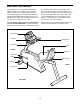
BEFORE YOU BEGIN Congratulations for selecting the new PROFORM¨ 985R recumbent cycle. Cycling is one of the most effective exercises for increasing cardiovascular fitness, building endurance, and toning the entire body. The PROFORM¨ 985R offers an impressive array of features to let you enjoy this healthful exercise in the convenience and privacy of your home. at 1-800-999-3756, Monday through Friday, 6 a.m. until 6 p.m. Mountain Time (excluding holidays).
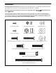
ASSEMBLY Assembly requires two persons. Place all parts of the recumbent cycle in a cleared area and remove the packing materials. Do not dispose of the packing materials until assembly is completed. Assembly requires the included tools and your own adjustable wrench driver . and Phillips screw- Use the part drawings below to identify the small parts used in assembly. The number in parenthesis below each drawing refers to the key number of the part, from the PART LIST on page 14.
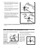
1. Attach the Front Stabilizer (2) to the front of the Frame (1) with two M10 x 70mm Carriage Bolts (72) and two M10 Nylon Locknuts (45). Make sure that the Front Stabilizer is turned so the Wheels (75) are not touching the floor. 1 72 2 75 1 45 2. Slide the Carriage Bar (7) onto the indicated tube on the Frame (1). Attach the Carriage Bar to the Frame with four M10 x 25mm Button Screws (74) and four M10 Split Washers (17).
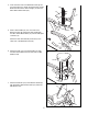
4. Insert the lower end of the Backrest Frame (8) into the Seat Frame (27). Attach the Seat Frame and the Backrest Frame to the Seat Carriage (11) with four M8 x 38mm Button Bolts (24). 4 24 24 27 8 11 5. Slide a Seat Handle (61) onto one side of the Backrest Frame (8). Attach the Seat Handle with two M6 x 38mm Button Bolts (14) and two M6 Nylon Locknuts (15). 5 8 Attach the other Seat Handle (not shown) to the other side of the Backrest Frame (8). 15 14 61 6.
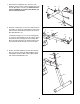
. While another person holds the Upright (6) in the position shown, connect the Extension Wire (18) to the Wire Harness (69). 8 Next, carefully slide the Upright (6) onto the Frame (1). Be careful to avoid pinching the wires. Loosely thread four M10 x 25mm Button Screws (74) with M10 Split Washers (17) into the Upright and the Frame. Then, firmly tighten all four Button Screws. 6 17 74 17 74 18 1 69 9.
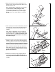
12. Identify the Left Pedal (40) (there is an ÒLÓ on the Left Pedal for identification). Using an adjustable wrench, tighten the Left Pedal counterclockwise into the left arm of the Crank (19). 12 41 Tighten the Right Pedal (not shown) clockwise into the right arm of the Crank (19). 40 Adjust the Left Pedal Strap (41) to the desired position and press the Pedal Strap onto the tab on the Left Pedal (40). Adjust the Right Pedal Strap (not shown) in the same way. Tab 19 13.
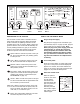
Program Profiles Mode Arrow Resistance Buttons Mode Button On/Reset Button DESCRIPTION OF THE CONSOLE Select Button HOW TO USE THE MANUAL MODE The innovative console offers a manual mode and three preset workout programs. When the manual mode is selected, the pedaling resistance can be changed with a touch of a button. When a preset programs is selected, the console will automatically control the pedaling resistance to give you an effective workout.
4 5 Adjust the pedaling resistance as desired. 6 Measure your heart rate, if desired. As you exercise, adjust the pedaling resistance by pressing the resistance buttons. The indicators on the left side of the Resistance console will show Indicators which resistance level is selected.
program P2, for example, the profile shows that the pedaling resistance will gradually increase during the first ten minutes, and then gradually decrease during the last ten minutes. HOW TO USE A PRESET WORKOUT PROGRAM 1 Plug in the power supply. See step 1 on page 10. 2 4 Turn on the power. As you exercise, the pedaling resistance will periodically change, as shown by the program profiles on the console. The indicators on the left side of the console will show the current resistance level.
CONDITIONING GUIDELINES The following guidelines will help you to plan your exercise program. Remember that proper nutrition and adequate rest are essential for successful results. Fat Burning To burn fat effectively, you must exercise at a relatively low intensity level for a sustained period of time. During the first few minutes of exercise, your body uses easily accessible carbohydrate calories for energy.
1 1 1 1 1 1 1 1 1 2 1 1 1 7 6 1 10 1 1 4 13 1 1 4 8 2 1 2 4 1 1 Frame Front Stabilizer Rear Stabilizer Left Side Shield Right Side Shield Upright Carriage Bar Backrest Frame Console Handlebar Endcap Seat Carriage Seat Backrest M6 x 38mm Button Bolt M6 Nylon Locknut Handlebar M10 Split Washer Extension Wire Pulley/Crank Console Screw M4 x 16mm Screw M10 Washer Frame Endcap M8 x 38mm Button Bolt M5 x 6mm Screw Seat Carriage Bushing Seat Frame Bushing M6 x 22mm Button Screw Pivot Bushing Magnet Descripti
17 2 40 41 62 21 42 19 77 72 17 74 74 6 20 74 45 4 39 75 72 17 21 78 56 57 47 48 67 12 60 76 21 51 29 48 47 83 59 55 70 46 21 26 11 27 24 58 76 34 87 57 56 76 90 25 29 81 49 50 52 21 52 76 46 83 21 45 92 21 66 21 36 44 53 84 45 31 16 15 73 76 54 62 45 80 1 17 74 17 32 69 32 18 77 42 74 17 82 71 19 5 21 62 79 88 28 25 25 88 24 74 69 43 25 13 30 90 10 17 89 33 65 26 17 87 28 29 EXPLODED DRAWINGÑModel No.
HOW TO ORDER REPLACEMENT PARTS To order replacement parts, simply call our Customer Service Department toll-free at 1-800-999-3756, Monday through Friday, 6 a.m. until 6 p.m. Mountain Time (excluding holidays).