www.proform.com Model No. PFBE19411.3 Serial No. Write the serial number in the space above for reference. Serial Number Decal ACTIVATE YOUR WARRANTY To register your product and activate your warranty today, go to www.proformservice.com/ registration. CUSTOMER CARE For service at any time, go to www.proformservice.com. Or call 1-888-533-1333 Mon.–Fri. 6 a.m.–6 p.m. MT Sat. 8 a.m.–12 p.m. MT Please do not contact the store.
TABLE OF CONTENTS WARNING DECAL PLACEMENT . . . . . . . . . . . . . . . . . . . . . . . . . . . . . . . . . . . . . . . . . . . . . . . . . . . . . . . . . . . . . . . 2 IMPORTANT PRECAUTIONS . . . . . . . . . . . . . . . . . . . . . . . . . . . . . . . . . . . . . . . . . . . . . . . . . . . . . . . . . . . . . . . . . . 3 BEFORE YOU BEGIN. . . . . . . . . . . . . . . . . . . . . . . . . . . . . . . . . . . . . . . . . . . . . . . . . . . . . . . . . . . . . . . . . . . . . . . .
IMPORTANT PRECAUTIONS WARNING: To reduce the risk of serious injury, read all important precautions and instructions in this manual and all warnings on your abdominal exerciser before using your abdominal exerciser. ICON assumes no responsibility for personal injury or property damage sustained by or through the use of this product. 1. It is the responsibility of the owner to ensure that all users of the abdominal exerciser are adequately informed of all precautions. 8.
STANDARD SERVICE PLANS all 4
BEFORE YOU BEGIN Thank you for selecting the PROFORM® AB GLIDER PLATINUM abdominal exerciser. The versatile AB GLIDER PLATINUM abdominal exerciser is designed to help you develop your core muscles, improve your muscle tone, achieve a shapelier gure, and increase your overall tness. after reading this manual, please see the front cover of this manual. To help us assist you, note the product model number and serial number before contacting us.
PART IDENTIFICATION CHART Use the drawings below to identify the small parts needed for assembly. The number in parentheses below each drawing is the key number of the part, from the PART LIST near the end of this manual. The number following the key number is the quantity needed for assembly. Note: If a part is not in the hardware kit, check to see if it has been preassembled. Extra parts may be included.
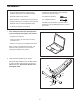
ASSEMBLY • To hire an authorized service technician to assemble this product, call 1-800-445-2480. • In addition to the included tool(s), assembly requires the following tool(s): • Assembly requires two persons. one Phillips screwdriver • Place all parts in a cleared area and remove the packing materials. Do not dispose of the packing materials until you nish all assembly steps. one adjustable wrench Assembly may be easier if you have a set of wrenches.
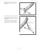
3. Attach the Frame Foot (11) to the underside of the Main Frame (1) with an M6 x 15mm Screw (28). 3 1 11 28 4. Insert the Sleeve (14) into the Front Stabilizer (4). 4 Next, orient the Front Stabilizer (4) as shown, and insert the leg on the Main Frame (1) into the Front Stabilizer. Then, insert the Incline Pin (51) into the Front Stabilizer (4) and into one of the three adjustment holes in the leg on the Main Frame (1).
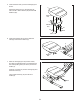
5. Orient the Knee Pad (7) and the Carriage (6) as shown. 5 7 Attach the Knee Pad (7) to the Carriage (6) with four M6 x 15mm Screws (28) and four M6 Washers (35). Wide End 6 Welded Bar 35 35 28 28 6. Orient the Carriage (6) as shown. Slide the Carriage onto the Pivot Frame (3). 6 3 Welded Bar 7. Move the Carriage (6) to the position shown, and align the indicated hole in the Carriage with the corresponding hole (not shown) in the Pivot Frame (3).
8. Note: There are two sets of holes near the lower end of the Handlebar (5); the Handlebar can be attached at either of two heights. 8 Attach the Handlebar (5) to the Main Frame (1) with two M8 x 145mm Bolts (30), four M8 Curved Washers (39), and two M8 Locknuts (38). 5 Tip: It may be helpful to use a hex key to turn each M8 x 145mm Bolt (30) while you insert it through the Handlebar (5) and the Main Frame (1). 30 39 39 38 1 9.
10. Remove the three M3 x 15mm Screws (24) from the Console (8), and remove the back of the Console. 10 8 Connect the wire on the Console (8) to the Reed Switch Wire (18) inside of the Pivot Frame (3). Then, insert the wires downward into the Pivot Frame. 18 8 24 31 3 48 Tip: Avoid pinching the wires. Attach the front and back of the Console (8) to the upper end of the Pivot Frame (3) as shown with two M4 x 20mm Screws (31) and two M4 Washers (48).
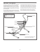
HOW TO USE THE ABDOMINAL EXERCISER HOW TO MOUNT AND DISMOUNT HOW TO LOCK THE PIVOT FRAME The pivot frame can swivel from side to side, and the knee pad can move forward and backward; to avoid losing your balance, use extreme caution while mounting and dismounting the abdominal exerciser. To prevent the Pivot Frame (3) from swiveling from side to side, insert the Lock Pin (27) into the Pivot Frame and the Main Frame (1).
FEATURES OF THE CONSOLE 3. Begin exercising and follow your progress with the display. The console features five modes that provide instant exercise feedback during your workouts: As you exercise, the console will provide instant exercise feedback. Scan—This mode displays the Time, Calorie, and Reps/ Min modes in a repeating cycle. 4. Reset the console, if desired. To reset the console display, press and hold the console button for several seconds until zeros appear in the display.
EXERCISE GUIDELINES Aerobic Exercise—If your goal is to strengthen your cardiovascular system, you must perform aerobic exercise, which is activity that requires large amounts of oxygen for prolonged periods of time. For aerobic exercise, adjust the intensity of your exercise until your heart rate is near the highest number in your training zone. WARNING: Before beginning this or any exercise program, consult your physician.
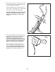
SUGGESTED STRETCHES The correct form for several basic stretches is shown at the right. Move slowly as you stretch; never bounce. 1. Toe Touch Stretch Stand with your knees bent slightly and slowly bend forward from your hips. Allow your back and shoulders to relax as you reach down toward your toes as far as possible. Hold for 15 counts, then relax. Repeat 3 times. Stretches: Hamstrings, back of knees and back. 1 2. Hamstring Stretch Sit with one leg extended.
NOTES 16
NOTES 17
PART LIST Key No. Qty. 1 2 3 4 5 6 7 8 9 10 11 12 13 14 15 16 17 18 19 20 21 22 23 24 25 26 27 28 1 1 1 1 1 1 1 1 2 4 1 2 1 1 1 1 2 1 2 2 2 1 1 3 4 4 1 5 Model No. PFBE19411.3 R1113A Description Key No. Qty.
EXPLODED DRAWING Model No. PFBE19411.
ORDERING REPLACEMENT PARTS To order replacement parts, please see the front cover of this manual.