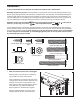
Model No. PFTL79506.3 Serial No. USER'S MANUAL Write the serial number in the space above for future reference. Serial Number Decal QUESTIONS? As a manufacturer, we are committed to providing complete customer satisfaction. If you have questions, or if parts are missing, PLEASE DO NOT CONTACT THE STORE; please contact Customer Care. IMPORTANT: You must note the product model number and serial number (see the drawing above) before contacting us: CALL TOLL-FREE: 1-888-533-1333 Mon.–Fri. 6 a.m.–6 p.m.
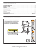
TABLE OF CONTENTS WARNING DECAL PLACEMENT . . . . . . . . . . . . . . . . . . . . . . . . . . . . . . . . . . . . . . . . . . . . . . . . . . . . . . . . . . . . . .2 IMPORTANT PRECAUTIONS . . . . . . . . . . . . . . . . . . . . . . . . . . . . . . . . . . . . . . . . . . . . . . . . . . . . . . . . . . . . . . . .3 BEFORE YOU BEGIN . . . . . . . . . . . . . . . . . . . . . . . . . . . . . . . . . . . . . . . . . . . . . . . . . . . . . . . . . . . . . . . . . . . . . .5 ASSEMBLY . . . . . . . . . . . . . .
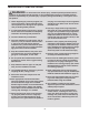
IMPORTANT PRECAUTIONS WARNING: To reduce the risk of serious injury, read all important precautions and instructions in this manual and all warnings on your treadmill before using your treadmill. ICON assumes no responsibility for personal injury or property damage sustained by or through the use of this product. carrying 15 or more amps. No other appliance should be on the same circuit. Do not use an extension cord. 1. Before beginning any exercise program, consult your physician.
20. Use the included dumbbells only as described in this manual. Properly store the dumbbells in the dumbbell holders on the console when you are not using them (see page 5). If the dumbbells are improperly stored, they may fall off the console, causing the user to trip. 23. When folding or moving the treadmill, make sure that the frame is held securely in the storage position. 24. Never insert any object into any opening on the treadmill. 25.
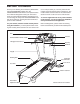
BEFORE YOU BEGIN Thank you for selecting the revolutionary PROFORM® 755 CROSSTRAINER treadmill. The 755 CROSSTRAINER treadmill offers an impressive selection of features designed to make your workouts at home more enjoyable and effective. And when you’re not exercising, the unique 755 CROSSTRAINER treadmill can be folded up, requiring less than half the floor space of other treadmills. ual. To help us assist you, note the product model number and serial number before contacting us.
3/4” Screw (2)–6 Star Washer (106)–4 Washer (38)–4 ASSEMBLY 2 1/2” Bolt (37)–2 To hire an authorized service technician to assemble the treadmill, call 1-800-445-2480. Wheel Nut (32)–2 materials. Do not 3 1/2” Bolt (45)–4 Assembly requires two persons. Set the treadmill in a cleared area and remove all packing dispose of the packing materials until assembly is completed. Note: The underside of the treadmill walking belt is coated with high-performance lubricant.
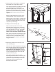
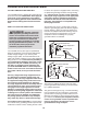
2. With the help of a second person, carefully tip the treadmill onto its right side as shown. 2 84 Insert the other Extension Leg (89) into the base of the Uprights (84) as shown. Hold two Extension Leg Nuts (67) in the bottom of the Extension Leg. Next, insert two Base Leg Bolts (65) into the top of the Extension Leg, and firmly tighten the Base Leg Bolts into the Extension Leg Nuts. 65 82 82 22 Attach two Base Pads (82) to the base of the Uprights (84) with two 3/4" Tek Screws (22).
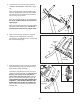
5. Lower the Frame (not shown) (see HOW TO LOWER THE TREADMILL FOR USE on page 19). 5 64 Have a second person hold the Handrail (20) near the Uprights (84). Insert the Wire Harness (77) into the hole in the bottom of the Handrail and out of the top as shown. 8 20 64 8 77 Next, set the Handrail (20) on the Uprights (84). Do not let the Wire Harness (77) fall into the right Upright.
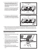
8. Set the console assembly on the Handrail (20). Be careful to avoid pinching any of the wires. Make sure that the ground wire (see step 6) and the wire harness from the console assembly (see step 7) are in the indicated channel. 8 Console Assembly Channel Partially tighten five Screws (3) into the Handrail (20) and the console assembly. Start all five Screws, but do not tighten them yet. Do not put Screws into the two indicated holes. 20 3 No Screws 3 9.
OPERATION AND ADJUSTMENT THE PRE-LUBRICATED WALKING BELT tric shock. This product is equipped with a cord having an equipment-grounding conductor and a grounding plug. Plug the power cord into a surge suppressor, and plug the surge suppressor into an appropriate outlet that is properly installed and grounded in accordance with all local codes and ordinances. Important: The treadmill is not compatible with GFCI-equipped outlets. Your treadmill features a walking belt coated with highperformance lubricant.
CONSOLE DIAGRAM Key Clip FEATURES OF THE CONSOLE The revolutionary treadmill console offers a selection of features designed to make your workouts more effective and enjoyable. ETPF79506 PFTL79506 When you select the manual mode of the console, you can change the speed and incline of the treadmill with the touch of a button. As you exercise, the console will display continuous exercise feedback.
HOW TO TURN ON THE POWER program has been selected, reselect the manual mode by pressing any of the four Programs buttons repeatedly until a track appears in the display. IMPORTANT: If the treadmill has been exposed to cold temperatures, allow it to warm to room temperature before turning on the power. If you do not do this, the console displays or other electrical components may become damaged. Plug in the power cord (see page 10).
5. Follow your progress with the display. 6. Measure your heart rate if desired. Note: The display features several different background colors. To select a background color, press the Display Color button repeatedly. Note: If you use the handgrip pulse sensor and the optional chest pulse sensor at the same time, the console will not display your heart rate accurately. When the manual mode is selected, the display will Track show a track that represents 1/4 mile (400 meters).
HOW TO USE A CROSS TRAINER PROGRAM may be programmed for two or more consecutive segments.) During other segments, the console will prompt you to perform strength exercises. 1. Insert the key into the console. During the program, the profile will show your progress. The Current Segment flashing segment of the profile represents the current segment of the program. The height of the flashing segment indicates the speed setting for the current segment.
5. Continue the cross trainer program. 4. Perform the first strength exercise when prompted. When you have performed the recommended number of repetitions, the words PRESS START will appear in the display. To continue the cross trainer program, step onto the treadmill, slide the clip back onto the waistband of your clothes, and press the Start button. The treadmill will automatically adjust to the speed and incline settings for the next segment.
HOW TO CREATE A CUSTOM PROGRAM one-minute segments. One speed setting and one incline setting can be programmed for each segment. The speed setting for the first segment will be shown in the flashing current segment column of the matrix. (The incline settings are not shown in the matrix.) To program a speed setting and an incline setting for the first segment, simply adjust the speed and incline of the treadmill as desired by pressing the Speed and Incline buttons.
HOW TO USE A CUSTOM PROGRAM 1. When the first segment is completed, all speed settings will move one column to the left. The speed setting for the second segment will then be shown in the flashing current segment column and the treadmill will automatically adjust to the speed and incline settings for the second segment. Insert the key into the console. See HOW TO TURN ON THE POWER on page 12. 2. Select one of the custom programs.
THE INFORMATION MODE Note: The console features a display demo mode, designed to be used if the treadmill is displayed in a store. While the demo mode is turned on, the console will function normally when you plug in the power cord, switch the circuit breaker to the reset position, and insert the key into the console. However, when you remove the key, the displays will remain lit, although the buttons will not function.
HOW TO FOLD AND MOVE THE TREADMILL HOW TO FOLD THE TREADMILL FOR STORAGE Before folding the treadmill, adjust the incline to the lowest position. If you do not do this, you may damage the treadmill when you fold it. Next, unplug the power cord. CAUTION: You must be able to safely lift 45 lbs. (20 kg) to raise, lower, or move the treadmill. Frame 1. Hold the metal frame firmly in the location shown by the arrow at the right.
TROUBLESHOOTING Most treadmill problems can be solved by following the steps below. Find the symptom that applies, and follow the steps listed. If you need further assistance, please see the front cover of this manual. PROBLEM: The power does not turn on SOLUTION: a. Make sure that the power cord is plugged into a surge suppressor, and that the surge suppressor is plugged into a properly grounded outlet (see page 10).
Locate the Reed Switch (63) and the Magnet (46) on the left side of the Front Roller (47). Turn the Front Roller until the Magnet is aligned with the Reed Switch. Make sure that the gap between the Magnet and the Reed Switch is about 1/8 in. (3 mm). If necessary, move the Reed Switch slightly using a slotted screwdriver. Reattach the Hood (not shown), making sure that the Screws (not shown) are inserted into the same holes from which they were removed.
EXERCISE GUIDELINES Burning Fat—To burn fat effectively, you must exercise at a low intensity level for a sustained period of time. During the first few minutes of exercise, your body uses carbohydrate calories for energy. Only after the first few minutes of exercise does your body begin to use stored fat calories for energy. If your goal is to burn fat, adjust the intensity of your exercise until your heart rate is near the lowest number in your training zone.
PART LIST—Model No. PFTL79506.3 R0108A To locate the parts listed below, see the EXPLODED DRAWING near the end of this manual. Key No. Qty.
5 16 24 55 53 52 7 69 90 23 21 5 9 102 70 22 3 5 1 53 51 54 7 49 19 23 21 18 5 9 22 90 48 6 30 5 70 17 11 12 58 5 50 10 102 3 97 15 102 3 1 5 29 47 46 12 10 11 5 6 19 30 18 3 96 102 101 39 15 EXPLODED DRAWING A—Model No. PFTL79506.
EXPLODED DRAWING B—Model No. PFTL79506.
EXPLODED DRAWING C—Model No. PFTL79506.
EXPLODED DRAWING D—Model No. PFTL79506.
ORDERING REPLACEMENT PARTS To order replacement parts, please see the front cover of this manual.