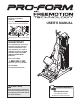
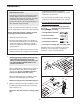
Model No. PFSY5806.0 Serial No. Write the serial number in the space above for future reference. USER’S MANUAL Serial Number Decal (Under Seat) QUESTIONS? As a manufacturer, we are committed to providing complete customer satisfaction. If you have questions, or if a part is damaged or missing, PLEASE CONTACT OUR CUSTOMER SERVICE DEPARTMENT DIRECTLY. CALL TOLL-FREE: 1-888-533-1333 Mon.–Fri., 6 a.m.–6 p.m. MST ON THE WEB: www.proformservice.
TABLE OF CONTENTS WARNING DECAL PLACEMENT . . . . . . . . . . . . . . . . . . . . . . . . . . . . . . . . . . . . . . . . . . . . . . . . . . . . . . . . . . . . . 2 IMPORTANT PRECAUTIONS . . . . . . . . . . . . . . . . . . . . . . . . . . . . . . . . . . . . . . . . . . . . . . . . . . . . . . . . . . . . . . . . 3 BEFORE YOU BEGIN . . . . . . . . . . . . . . . . . . . . . . . . . . . . . . . . . . . . . . . . . . . . . . . . . . . . . . . . . . . . . . . . . . . . . . 4 ASSEMBLY . . . . . . . . . . . . .
IMPORTANT PRECAUTIONS WARNING: To reduce the risk of serious injury, read the following important precautions before using the weight system. 1. Read all instructions in this manual and all warnings on the weight system before using the weight system. Use the weight system only as described in this manual. 10. Make sure that the cables remain on the pulleys at all times. If the cables bind as you are exercising, stop immediately and make sure that the cables are on the pulleys.
BEFORE YOU BEGIN manual. To help us assist you, please note the product model number and serial number before contacting us. The model number is PFSY5806.0. The serial number can be found on a decal attached to the weight system (see the front cover of this manual). Thank you for selecting the versatile PROFORM® WITH FREEMOTION TECHNOLOGY weight system. The weight system offers a selection of weight stations designed to develop every major muscle group of the body.
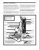
ASSEMBLY materials until assembly is completed. • Tighten all parts as you assemble them, unless instructed to do otherwise. Make Assembly Easier Everything in this manual is designed to ensure that the weight system can be assembled successfully by almost anyone. However, the weight system has many parts and the assembly process will take time. By setting aside plenty of time, assembly will go smoothly. • As you assemble the weight system, make sure all parts are oriented as shown in the drawings.
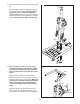
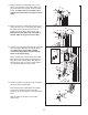
3. Press the 89mm Round Cap (39) into the Upright (3). 3 39 Insert four M10 x 55mm Carriage Bolts (83) up through the Base (1). Note: Covering the bolt heads with a piece of tape may help hold them in place. Attach the Upright (3) to the Base with the four Bolts and four M10 Nylon Locknuts (108). Do not tighten the Nylon Locknuts yet. 3 108 108 1 83 83 4. Note: The parts in steps 7, 13, and 14 may come preassembled.
5. Attach the Weight Guide (13) to the Base (1) with an M10 x 50mm Bolt (96), two M10 Washers (105), an 16mm x 6mm Spacer (11), and an M10 Nylon Locknut (108). 5 16 79 Attach the Weight Guide With Hole (36) to the Base (1) in the same manner. Make sure that the indicated hole in the Weight Guide is closer to the bottom. 13 36 27 Locate the fourteen Weights (27) that do not have Weight Bushings (30) pressed into them. Press two Weight Bushings into the outside holes of each Weight.
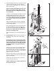
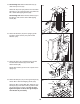
7. Refer to the CABLE DIAGRAM on page 17 to ensure correct cable routing during steps 7 through 14. 7 66 Use the wire in the Left Press Arm (7) to pull the Press Arm Cable (66) up through the Press Arm. Make sure that the Cable is routed around the pulleys above the Press Arm as shown in the inset drawing. Hold a 4" Pulley (42) over the Press Arm Cable (66).
11. Route the Press Arm Cable (66) over a 3 1/2" Pulley (43). Attach the Pulley and a Cable Trap (47) to the Top Frame (12) with an M10 x 40mm Screw (97). Make sure that the Cable Trap is oriented to hold the Cable in the groove of the Pulley. 11 12. Route the Press Arm Cable (66) through the Top Cover (24) and over a 3 1/2" Pulley (43). Attach the Pulley and a Cable Trap (47) to the Top Frame (12) with an M10 x 40mm Screw (97).
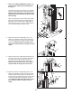
15. See drawing 15a. Slide the Rear Shroud (15) under the Top Cover (24). 15a 24 99 99 Attach the Top Cover (24) and the Front and Rear Shrouds (14, 15) to the Top Frame (12) with three M4 x 16mm Self-tapping Screws (99). 12 15 14 See drawing 15b. Attach the Rear Shroud (15) to the Base (1) with an M4 x 16mm Self-tapping Screw (99). 15b 99 15 1 16. Attach the Backrest (18) to the Upright (3) with two M6 x 115mm Screws (113) and two M6 Washers (107). 16 3 113 107 18 113 107 17.
19. Attach a Front and Rear Dip Cap (33, 34) around a Dip Handle (10) with two M3 x 32mm Self-tapping Screws (102). 19 5 51 Tighten a Dip Arm Knob (51) into the Dip Arm (5). Pull the Knob out as far as it will go and insert the Dip Handle (10) through a Dip Arm Bushing (35) and into the Dip Arm. Engage the Knob into the Dip Handle. 102 10 35 33 34 102 Repeat this step on the other side of the Dip Arm (5). 20.
ADJUSTMENTS This section explains how to adjust the weight system. See the EXERCISE GUIDELINES on page 18 for important information about how to get the most benefit from your exercise program. Also, refer to the accompanying exercise guide to see the correct form for each exercise. Properly tighten all parts each time the weight system is used. Replace any worn parts immediately. The weight system can be cleaned with a damp cloth and a mild, non-abrasive detergent. Do not use solvents.
ADJUSTING THE SEAT 3 19 To adjust the height of the Seat (19), lift the Seat Frame (4) off of the Upright (3). Set the Seat Frame onto a different set of posts on the Upright. 4 For some exercises, the Seat (19) should be removed from the weight system and stored where it will not interfere with the exercise. ATTACHING THE CURL PAD 20 To use the Curl Pad (20), insert the Curl Post (9) into the Seat Frame (4). Secure the Curl Post with the Curl Knob (52).
ATTACHING THE CURL BAR To use the Curl Bar (58), first attach the curl pad to the seat frame (see ATTACHING THE CURL PAD on page 13). Next, attach the pulley housings to the preacher curl position (see ATTACHING THE PULLEY HOUSINGS on page 13). Then, attach the Housing Cables (71) to the Leg Developer (6) with two Clips (not shown). Finally, attach the Curl Bar to the Leg Developer with a Clip (61).
MOVING THE WEIGHT SYSTEM To move the weight system, step on the levers on the Locking Casters (76) to unlock the wheels. Move the weight system to the new location. Relock the wheels on the Locking Casters. Lever 76 CHANGING THE WEIGHT SETTING To change the setting of the weight stack, insert the Weight Pin (28) under the desired Weight (27). Insert the Weight Pin so that the bent end touches the weight stack. Turn the bent end down.
WEIGHT RESISTANCE CHART The chart below shows the approximate weight resistance for the 10 lb. weights. Note: The actual resistance at each station may vary due to differences in individual weight plates as well as friction between the cables, pulleys, and weight guides. *Weight resistance shown is for each arm.
CABLE DIAGRAM The cable diagram shows the proper routing of the Press Arm Cable (66). Use the diagram to make sure that the cable and the cable traps have been assembled correctly. If the cable has not been correctly routed, the weight system will not function properly and damage may occur. The numbers show the correct route for the cable. Make sure that the cable traps do not touch or bind the cable.
EXERCISE GUIDELINES THE FOUR BASIC TYPES OF WORKOUTS PERSONALIZING YOUR EXERCISE PROGRAM Muscle Building To increase the size and strength of your muscles, push them close to their maximum capacity. Your muscles will adapt and grow as you progressively increase the intensity of your exercise. You can adjust the intensity level of an individual exercise in two ways: • by changing the amount of weight used • by changing the number of repetitions or sets performed.
slowly as you stretch and do not bounce. Ease into each stretch gradually and go only as far as you can without strain. Stretching at the end of each workout is an effective way to increase flexibility. Rest for a short period of time after each set. The ideal resting periods are: • Rest for three minutes after each set for a muscle building workout. • Rest for one minute after each set for a toning workout. • Rest for 30 seconds after each set for a weight loss workout.
PART LIST—Model No. PFSY5806.0 Key No. 1 2 3 4 5 6 7 8 9 10 11 Qty.
PART IDENTIFICATION CHART Refer to the drawings below to identify small parts used in assembly. The number in parentheses by each drawing is the key number of the part, from the PART LIST in the center of this manual. Note: Some small parts may have been pre-attached. If a part is not in the parts bag, check to see if it has been pre-attached.
EXPLODED DRAWING A—Model No. PFSY5806.
EXPLODED DRAWING B—Model No. PFSY5806.
ORDERING REPLACEMENT PARTS To order replacement parts, please see the front cover of this manual. To help us assist you, be prepared to give the following information: • the MODEL NUMBER of the product (PFSY5806.