
Owner's Manual

7
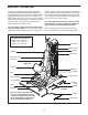
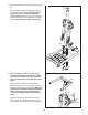
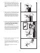
5. Attach the Weight Guide (13) to the Base (1) with
an M10 x 50mm Bolt (96), two M10 Washers
(
105), an 16mm x 6mm Spacer (11), and an M10
Nylon Locknut (108).
Attach the Weight Guide With Hole (36) to the
Base (1) in the same manner. Make sure that
the indicated hole in the Weight Guide is clos-
er to the bottom.
Locate the fourteen Weights (27) that do not have
Weight Bushings (30) pressed into them. Press
two Weight Bushings into the outside holes of
each Weight.
Make sure that all of the Weights
are oriented as shown with the pin holes on
the bottom.
Slide two Weight Bumpers (29) onto the Weight
Guides (13, 36). Slide the fourteen Weights (27)
onto the Weight Guides.
Insert the Weight Tube (16) into the center hole in
the fifteenth Weight (27). Tap the Roll Pin (79)
into the top hole in the Weight Tube.
Make sure
that the Pin is underneath the Weight and is
centered in the Weight Tube.
Slide the Weight (27) onto the Weight Guides (13,
36).
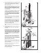
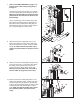
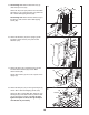
6. See drawing 6b. Attach the Front Shroud (14) to
the Base (1) with an M4 x 16mm Self-tapping
Screw (99).
See drawing 6a. Note: If the Press Arm Cable
(not shown) has been routed through the Top
Cover (24), make sure that the Cable crosses
under the Top Frame (12) and hangs between
the Weight Guides (13, 36) while this step is
completed.
Attach the
T
op Frame (12) to the Weight Guides
(13, 36) with two M10 x 65mm Bolts (95), four
M10 Washers (105), two 16mm x 12mm Spacers
(81), and two M10 Nylon Locknuts (108).
Do not
tighten the Nylon Locknut yet.
Attach the Top Frame (12) to the Upright (3) with
two M10 x 100mm Button Bolts (91) and an M10
Nylon Locknut (108).
Set the Top Cover (24) over the Front Shroud
(14) and the Top Frame (12).
Tighten the M10 Nylon Locknuts (108) used in
this step and in step 3.
16
79
36
13
5
27
30
27
29
Hole
96
11
1
105
108
Pin
Hole
12
95
105
108
6a
6b
99
14
1
14
3
81
108
105
105
13
36
24
91