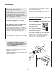
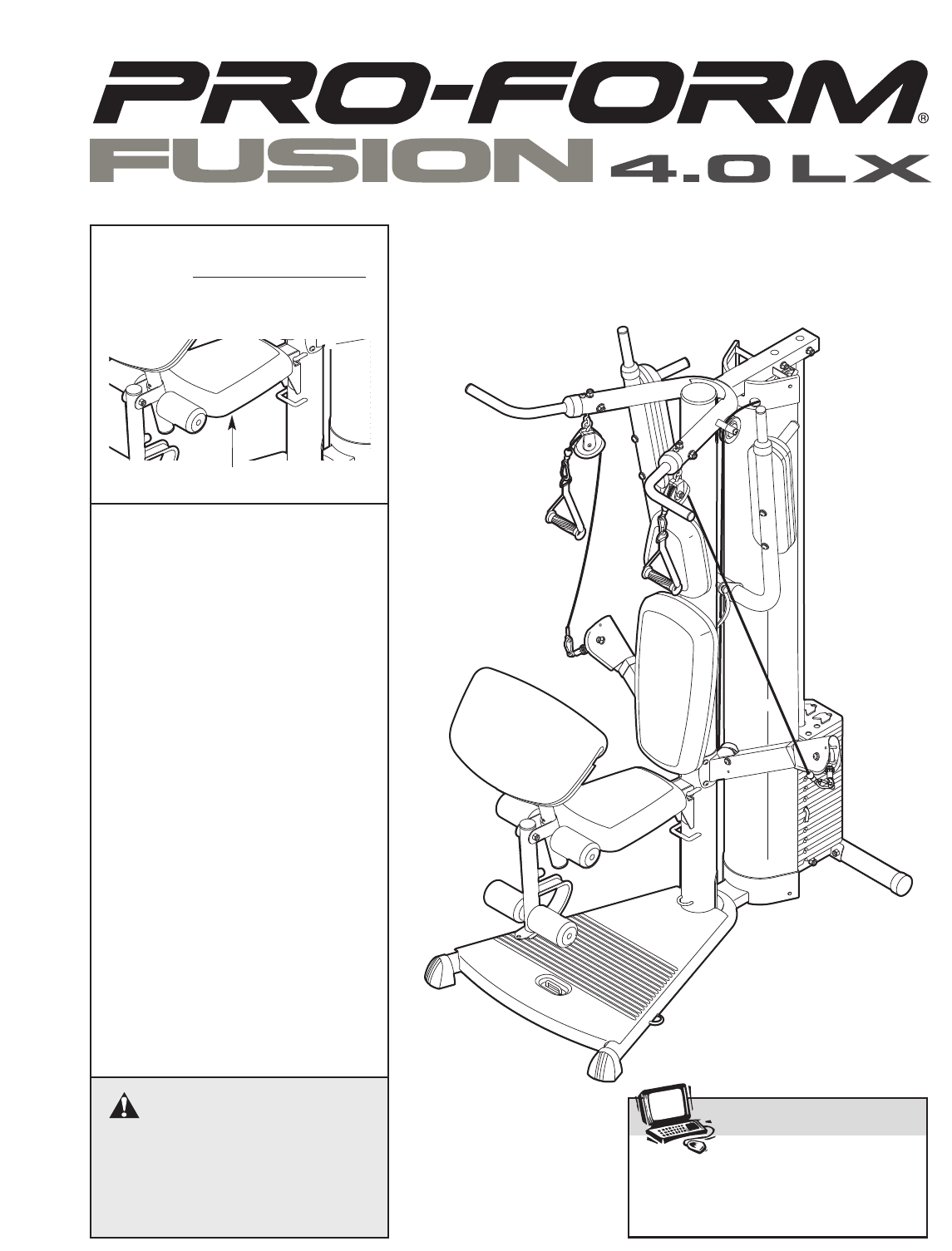
Model No. PFSY3415.0 Serial No. Write the serial number in the space above for future reference. USER’S MANUAL Serial Number Decal (Under Seat) QUESTIONS? As a manufacturer, we are committed to providing complete customer satisfaction. If you have questions, or if a part is damaged or missing, PLEASE CONTACT OUR CUSTOMER SERVICE DEPARTMENT DIRECTLY. CALL TOLL-FREE: 1-888-533-1333 Mon.–Fri., 6 a.m.–6 p.m. MST ON THE WEB: www.proformservice.
TABLE OF CONTENTS WARNING DECAL PLACEMENT . . . . . . . . . . . . . . . . . . . . . . . . . . . . . . . . . . . . . . . . . . . . . . . . . . . . . . . . . . . . . 2 IMPORTANT PRECAUTIONS . . . . . . . . . . . . . . . . . . . . . . . . . . . . . . . . . . . . . . . . . . . . . . . . . . . . . . . . . . . . . . . . 3 BEFORE YOU BEGIN . . . . . . . . . . . . . . . . . . . . . . . . . . . . . . . . . . . . . . . . . . . . . . . . . . . . . . . . . . . . . . . . . . . . . . 4 ASSEMBLY . . . . . . . . . . . . .
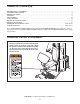
IMPORTANT PRECAUTIONS WARNING: To reduce the risk of serious injury, read the following important precautions before using the weight system. 1. Read all instructions in this manual and all warnings on the weight system before using the weight system. Use the weight system only as described in this manual. 9. Always wear athletic shoes for foot protection while exercising. 10. Always stand on the foot plate when performing an exercise that could cause the weight system to tip. 2.
BEFORE YOU BEGIN Thank you for selecting the versatile PROFORM® FUSION 4.0 LX weight system. The weight system offers a selection of weight stations designed to develop every major muscle group of the body. Whether your goal is to tone your body, build dramatic muscle size and strength, or improve your cardiovascular system, the weight system will help you to achieve the specific results you want. model number and serial number before calling. The model number is PFSY3415.0.
ASSEMBLY • Tighten all parts as you assemble them, unless instructed to do otherwise. Make Things Easier for Yourself Everything in this manual is designed to ensure that the weight system can be assembled successfully by almost anyone. However, the weight system has many parts and the assembly process will take time. By setting aside plenty of time, assembly will go smoothly. • As you assemble the weight system, make sure all parts are oriented as shown in the drawings. • Assembly requires two people.
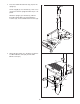
2. Press the 110mm Round Inner Cap (42) into the Upright (3). 2 42 Set the Upright (3) onto the Base (1). Have a second person hold the Upright until this step is completed. Attach the Upright (3) to the Base (1) with the three M8 x 45mm Bolts (57), three M8 Nylon Locknuts (74), and four M10 x 25mm Screws (58). 3 58 58 74 57 1 74 57 3. Attach the Base Plate (2) to the Base (1) with the four M4 x 40mm Screws (46), and two M4 x 64mm Screws (81).
4. Insert the Weight Tube (11) into a Weight (17). Make sure the indicated slot in the Weight is oriented as shown. Center the Roll Pin (54) into the indicated hole in the Weight Tube. Note: The Roll Pin must be below the Weight. 4 54 11 17 Slot 5. Orient the two Weight Guides (10) with the indicated hole closer to the bottom (see the inset drawing). 5 10 10 Insert the two Weight Guides (10) into the indicated holes in the Base (1).
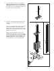
6. Slide three M6 Washers (78) onto three M6 x 140mm Screws (79) and insert the Screws into the Upright (3) through the indicated holes. 6 Orient the VKR Bumper (95) with the wide end on top. Attach the VKR Bumper to the Upright (3) with two M4 x 16mm Screws (70). Attach the VKR Pin (101) to the Upright (3) with an M4 x 16mm Screw (70). 79 78 Set the Shroud (13) onto the Base (1). Attach the Bottom Cover (14) and the Shroud to the Base with two M4 x 16mm Screws (70).
8. Slide the Top Frame (4) onto the Weight Guides (10). Attach the Top Frame to the Weight Guides with two M8 x 89mm Bolts (64), four M8 Washers (72), two 25mm Spacers (47), and two M8 Nylon Locknuts (74). Do not tighten the Locknuts. 8 64 47 72 72 Attach the Top Frame (4) to the Upright (3) with four M10 x 25mm Screws (58). Do not tighten the Screws. 74 4 Attach the Top Cover (15) to the Shroud (13) and Top Frame (4) with two M4 x 16mm Screws (70).
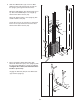
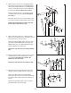
12. Attach a “V”-pulley (22) to a Swivel Arm (16) with an M10 x 64mm Button Bolt (75), two M10 Washers (71), two 5mm Spacers (25), and an M10 Nylon Locknut (73). Make sure the Press Arm Cable (30) is routed under the indicated welded rods. 12 16 Welded Rod 25 71 73 71 30 75 25 Welded Rod 13. Attach a 2 3/4" Pulley (23) to the left Press Arm (8) with an M10 x 53mm Button Bolt (61), two M10 Washers (71), two 5mm Spacers (25), two Finger Guards (27), and an M10 Nylon Locknut (73). See the inset drawing.
16. Wrap the Press Arm Cable (30) under a 3 1/2" Pulley (24). Attach the Pulley, a Cable Trap (28), and two Half Finger Guards (26) to the Weight Tube (11) with an M10 x 48mm Bolt (62) and an M10 Nylon Locknut (73) at the indicated hole. Make sure the Finger Guards are oriented as shown and are on the outside of the Weight Tube. Make sure the Cable Trap is oriented to hold the Cable in the groove of the Pulley. 16 17. Wrap the Press Arm Cable (30) over a 3 1/2" Pulley (24).
20. Attach a 2 3/4" Pulley (23) to the right Press Arm (8) with an M10 x 53mm Button Bolt (61), two M10 Washers (71), two 5mm Spacers (25), two Finger Guards (27), and an M10 Nylon Locknut (73). See the inset drawing. Orient the Finger Guards and Pulley as shown. Make sure the Press Arm Cable (30) is in the groove of the Pulley. 20 73 25 71 27 27 25 30 27 8 23 27 61 71 21. Make sure the Press Arm Cable (30) is routed under the indicated welded rods.
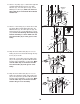
24. Attach the Seat (19) and the Seat Base (91) to the Seat Frame (6) with two M6 x 25mm Screws (60), an M6 x 87mm Screw (68), and an M6 Washer (78). 24 19 91 Hook the Seat Frame (6) onto the Upright (3) at the indicated location. 3 6 25. Attach the Bumper (49) to the Leg Lever (7) with an M4 x 16mm Screw (70). 78 68 60 25 Grease Apply grease to an M10 x 71mm Bolt (67). Attach the Leg Lever (7) to the Seat Frame (6) with the Bolt and an M10 Nylon Locknut (73).
28. Attach the Curl Pad (87) and the Curl Pad Base (86) to the Curl Post (85) with two M6 x 25mm Screws (60). 28 60 87 86 85 29. Make sure that all parts have been properly tightened before the resistance system is used. ADJUSTMENTS This section explains how to adjust the weight system. See the EXERCISE GUIDELINES on page 18 for important information about how to get the most benefit from your exercise program. Also, refer to the accompanying exercise guide to see the correct form for each exercise.
ATTACHING THE HANDLES To attach a Handle (33), first attach the pulley housings to the weight system (see ATTACHING THE PULLEY HOUSING on page 14 above). Then, attach the Handle to an Extension Cable (31) with a Cable Clip (37). The Handles can be attached to the Press Arm Cable (30) in the same manner. 31 37 The Ankle Strap (not shown) or Squat Bar (not shown) can be attached to an Extension Cable (31) in the same manner.
ATTACHING THE LEG LEVER To use the Leg Lever (7), first attach the seat to the weight system (see ADJUSTING THE SEAT FRAME HEIGHT on page 15). Then, attach the pulley housings to the upright (see ATTACHING THE PULLEY HOUSINGS on page 14). Finally, attach the Extension Cables (31) to the Chain (107) with two Cable Clips (37) and attach the Chain to the Leg Lever with another Cable Clip. Note: For less resistance, the Leg Lever can be used with only one Extension Cable attached to it.
CABLE DIAGRAM The cable diagram shows the proper routing of the Press Arm Cable (30). Use the diagram to make sure that the Cable has been assembled correctly. If the Cable has not been correctly routed, the weight system will not function properly and damage may occur. The numbers show the correct route for the Cable. Press Arm Cable (30) 6 7 4 3 5 9 8 2 1 WEIGHT RESISTANCE CHART The chart below shows the approximate weight resistance for the 12.5 lb. weights.
EXERCISE GUIDELINES THE FOUR BASIC TYPES OF WORKOUTS PERSONALIZING YOUR EXERCISE PROGRAM Muscle Building To increase the size and strength of your muscles, push them to a high percentage of their maximum capacity. Your muscles will adapt and grow as you progressively increase the intensity of your exercise. You can adjust the intensity level of an individual exercise in two ways: • by changing the amount of weight used • by changing the number of repetitions or sets performed.
slowly as you stretch and do not bounce. Ease into each stretch gradually and go only as far as you can without strain. Stretching at the end of each workout is an effective way to increase flexibility. Rest for a short period of time after each set. The ideal resting periods are: • Rest for three minutes after each set for a muscle building workout. • Rest for one minute after each set for a toning workout. • Rest for 30 seconds after each set for a weight loss workout.
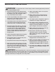
PART IDENTIFICATION CHART Refer to the drawings below to identify small parts used in assembly. The number in parentheses by each drawing is the key number of the part, from the PART LIST in the center of this manual. Note: Some small parts may have been pre-attached. If a part is not in the parts bag, check to see if it has been pre-attached.
PART LIST—Model No. PFSY3415.0 Key No. Qty.
EXPLODED DRAWING A—Model No. PFSY3415.
EXPLODED DRAWING B—Model No. PFSY3415.
ORDERING REPLACEMENT PARTS To order replacement parts, see the front cover of this manual. To help us assist you, please be prepared to give the following information 1. the MODEL NUMBER of the product (PFSY3415.0) 2. the NAME of the product (PROFORM FUSION 4.0 LX weight system) 3. the SERIAL NUMBER of the product (see the front cover of this manual) 4.