
User's Manual


D
Note: If you have a PROFORM 785Pi or model number
PFTL79100, please call 1-800-999-3756.
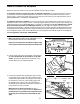
1. Make sure that the power cord is unplugged. Remove
the indicated Screws (A) from the Console Back (B).
Remove the Console Back from the Console Base (E).
2. Locate the loose Pulse Wire (C) inside the Console Base
(E). Connect the Pulse Wire to the wire on the Receiver
(D). Next, peel the paper off the pad on the bottom of the
Receiver. Turn the Receiver so the cylinder is on the
side shown, hold the Receiver inside of the Console
Base (E), and press the Receiver onto the bottom of the
Console Base in the location indicated by the dotted line.
Note: The wires included with the receiver may be dis-
carded. The Wire Tie can be used to tie wires, if needed.
Make sure that no wires are pinched. See step 1.
Reattach the Console Back (B) with the Screws (A).
B
E
A
1
C
2
Cylinder
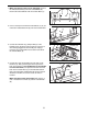
1. Make sure that the power cord is unplugged. Remove
the Screws (A) from the Console Back (B). If the Screws
are different lengths, make sure that they are re-
turned to the same holes at the end of step 2. Remove
the Console Back from the Console Base (C). Note: The
number of Screws and the locations of the Screws may
vary depending on the model of your treadmill. There
may also be a Screw in a Small Clamp (H) under each
Cup Holder (G).
2. Connect the included Long Jumper Wire (D) to the
PULSE #1 jack on the back of the Console (E) (see the
inset drawing). Connect the other end of the Long Jumper
Wire to the wire on the Receiver (F). Next, peel the paper
off the pad on the back of the Receiver. Turn the
Receiver so the cylinder is on the side shown, and
press the Receiver onto the back of the Console Base (C)
in the indicated location. Note: The other wires included
with the receiver may be discarded. The Wire Tie can be
used to tie wires, if needed.
Make sure that no wires are pinched. Refer to step 1
and reattach the Console Back (B). See the inset drawing
in step 1. Make sure the Small Clamps (H) are looped
through the holes in the bottoms of the Cup Holders (G)
and attach them with the same Screws removed in step 1.
B
A
1
PULSE #1
2
PULSE Jack
E
C
C
D
F
Cylinder
E
6
A
G
G
G
H